I should have been more descriptive to clarify the point.
The thing is that once you add/change anything in Reach software, it’s becoming difficult to predict how Reach and ReachView will perform. When we add new features or fixes, we thoroughly test the code for a long time to make sure it’s stable.
That’s why when we are asked about coding onboard of Reach, we are very limited with suggesting anything because we can’t see the whole picture and predict how the things you are implementing can affect main functionality.
You are free to do whatever you need to accomplish the task and perhaps community users will have any suggestions.
However, I’d recommend checking for other options. For instance, you can output the position from Reach on 3rd-party board (Arduino or RPi) and run your script there.
Please don’t hesitate to create more topics, we really appreciate you are with us here.
That is a good question. First I have to assume you are talking about a Velodyne LiDAR unit because I am not familiar with others. (They may or may not have the same requirements). Having said that the primary difficulty with integration is synchronized timing of the different devices. The second issue is orientation. You’ll need a high quality IMU for that. The Reach M+ seems to have PPS output and thus it’s possible to use that via some kind of clock buffer to split the PPS signal from the M+ to both the IMU and the LiDAR. The third difficulty is the GNSS. There are 2 issues with the GNSS; 1) the polarity of the TX signal and 2) whether $GPRMC or $GNRMC is being sent. I don’t yet have a M+ module but I assume it is the same as the original Reach module in these 2 GNSS issues. So you will have to invert the the polarity of the TX signal via a Logic NOT gate and you will have to replace/convert the $GNRMC to $GPRMC. The issues regarding PPS and GNSS must be dealt with or the Velodyne puck won’t be able to sync to and recognize time from the reach module. Once you have the Puck locked on good GPS coordinates it will also have good time (in microseconds past the hour). Now you just need to get orientation data from the IMU. Given data that is all synced in time you should be able to pull everything together to build a nice point cloud that you’ll then need to save in a format like LAS that you can then review in something like CloudCompare.
Here’s the problem I see with trying to use the Reach M+: While it can (seemingly) output PPS it does not output $GPRMC (I assume). It outputs $GNRMC (like the original Reach module). The problem is that the Velodyne puck does not recognize $GNRMC so it can’t get time from it. It might be possible to convert the $GNRMC outside of the module but then you are faced with a potential timing slip (due to the amount of time required to do the conversion). That tiny little slip can easily cause really ugly results in the final point cloud.
Hopefully someone will correct my assumptions about the Reach M+ because I would like to try it without having to run custom code on it to modify $GNRMC. Which even if I did I still might have to deal with timing slips as I am now experiencing with my custom code running on the original Reach module.
An ideal situation would be that the puck would recognize the $GNRMC. Maybe Velodyne will accommodate?
BTW:
The first 2 letters after the $ sign in the NMEA message is the Talker ID and indicates the nature and source of information:
GP: GPS; GL: Glonass; GA: Gallileo; GN: combinded GNSS systems
(defined in the NMEA specification)
The u-ublox receivers can be configured how to use the talker IDs with the binary UBX-CFG-NMEA message.
In order to get GPRMC messages the Main Talker ID has to be changed to GP(GPS).
However I’m not sure how this will effect the rest of the system. It may be that changing the Talker ID will disable the other satellite information.
So, I put in a request at Velodyne that they support $GNRMC as well as $GPRMC. I’m hoping that since the 2 messages are identical except for the “N” and “P” it should be little effort for them to support both. We’ll see…
I almost forgot…
There there is one other issue: The puck want’s PPS set to 1 per second and to only be sent the single $GPRMC that must end within 500ms of the PPS rising edge and they want it sent at 9600 baud. In my testing I have found that the puck can handle multiple different messages but they must end at the 500ms mark or the puck has trouble synchronizing. The Reach module (at least the original) is sending many different messages 5 times per second so at at 9600 baud they take longer than 500ms. This could be solved by either having Reach module NMEA message configurable (not likely since they need everything they are currently getting) or by the puck handling a higher baud rate. I’ll request that later if they decide to support GN as well as GP.
I can confirm that you can integrate the original Reach Rover and Base with a Velodyne VLP-16 puck and a VectorNav VN-100.
No changes were necessary to the VLP-16 firmware however I did need to run custom software on the Reach rover to redirect PPS output and modify the NEMA message stream and redirect it out the serial port.
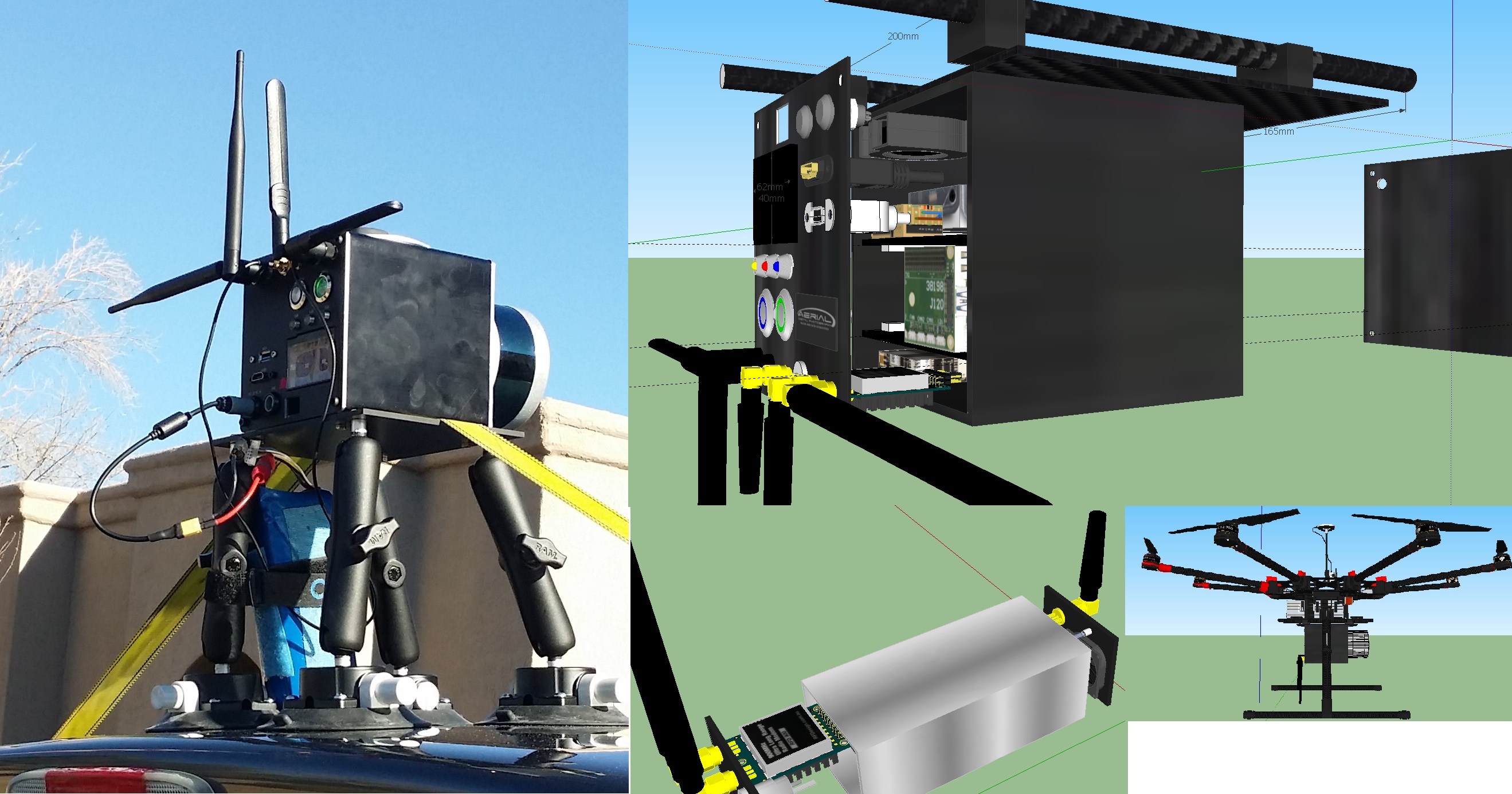
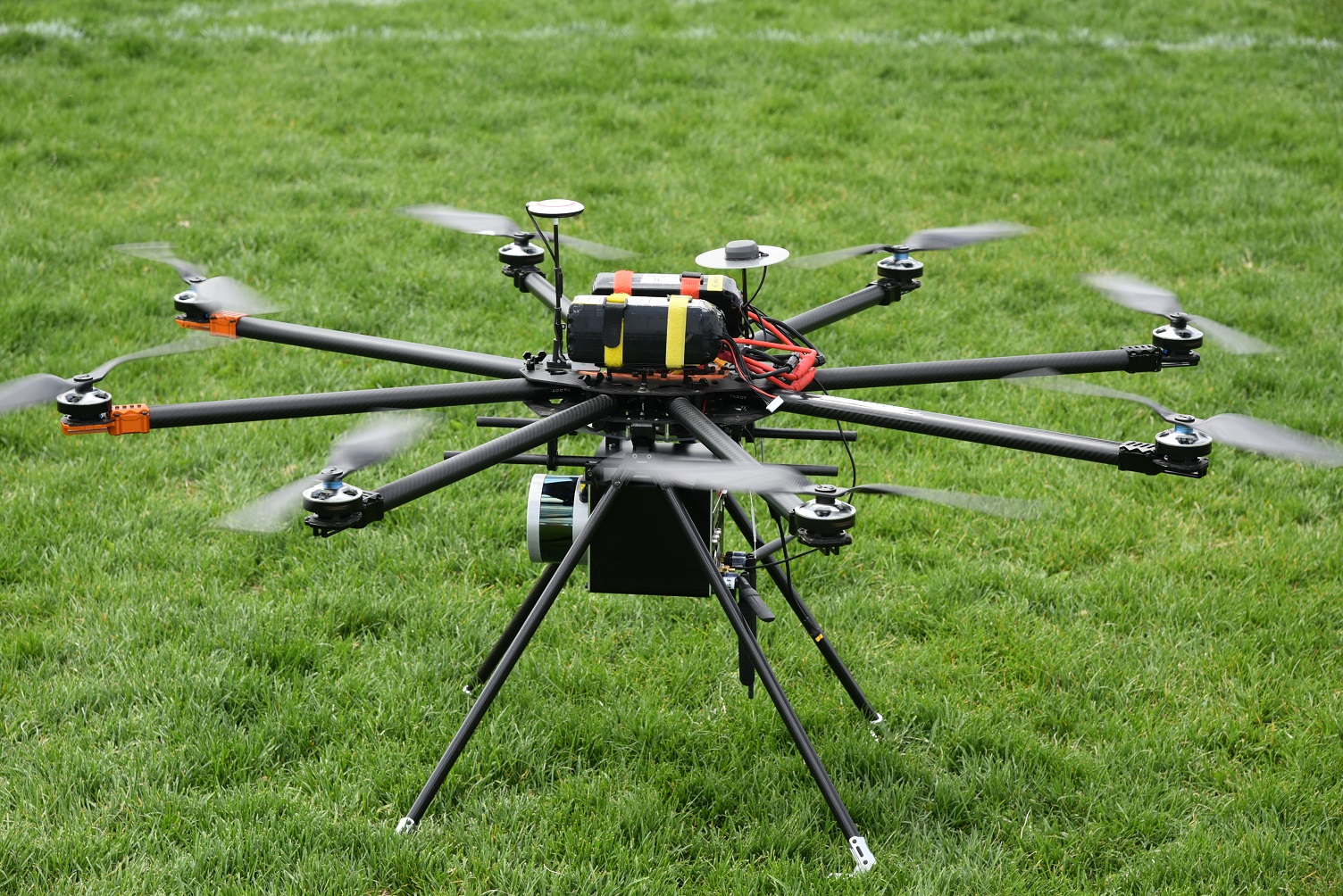
This was accomplished via a custom LiDAR system I built and bolted to the back of my truck as I drove around the block in my neighborhood.
More info including code, images and design documentation is available.
If you want to do something like this let me know and I’ll do what I can to help.
Very nice work Scott ! Such integration should cut the price for a full lidar system by a nice amount. Off the shelf they are still quite elitist tools.
I saw Ouster OS-1 starting at $3,500 for a 16 channel (12,000 for 64), VN-100 at $800 and of course Reach. Guys like you should sell pretty cool integration boards. You could valuate your work.
I am very curious to have a general view of your setup, and also what kind of accuracy you can get from your point cloud ?
Accuracy is kind of difficult to be precise about. Generally it is as accurate as the data allows. By this I mean it depends a lot on the accuracy of the devices being used and how they are configured. Each device has a range.
VLP-16 - Depends on distance to reflected object
VN-100 - Depends on internal accuracy but improved via velocity aiding but that accuracy (which is derived from data coming from the Reach) depends on the Reach.
Reach RTK - depends on many factors including fix type and navigation rate.
Accuracy is still to be determined as we are still testing basic features. My guess is that it will be mostly limited by the type of RTK fix we can maintain while capturing points. Probably within a few centimeters. Ultimately we’ll be comparing what we generate with other clouds generated via photo capture. The real question is how well will it register with the clouds we generate via Dronedeploy for example. I don’t know yet.
I probably need to take some better pictures but here’s a quick-n-dirty mashup:
Not shown there is also software to control it via Wi-Fi from a laptop on the ground (windows). I may also write an app to control it from my phone (android).
Scott, I would rather say that accuracy is mainly a function of how do you arrange all data together : Lidar, attitude, positioning + all the possible offsets between them, angular, distance and latency.
Individual sensors being in general chosen for the reliability of their data, i.e. lidar giving good distances to objects or good roll & pitch from IMU.
I do quite a lot of multibeam bathymetry and the analogy is almost perfect between sensors. And there results are all dependant of good calibration to evaluate each individual offset. The ultimate criteria being to get a continuous surface of the seabed when you gather the data from various directions and speeds : opposite direction same runline, right / left overlap, same direction double speed, cross lines… And of course comparison with known location.
You should not bother too much with RTK, PPK is probably the good option as you still have to post-process other data. RTK in urban areas is a nightmare. But you probably have your reasons to go for this solution.
You may be right. We are in the process of boresighting the sensors and that may turnout to be the achilles heel of the system. My assumption is that once that is properly done then the ultimate accuracy will come down to the items I mentioned. Ideally the calibration phase will be semi automatic. I’m thinking along the lines of a few figure eights (with the associated analysis and adjustments) prior to actual capturing. However I’ll be the first to admit that I may be somewhat naive when it comes to this. I’m ok with that. This project is primarily a learning endeavor so I expect to make a few (or maybe a lot of) mistakes.
Nice work, Scott. I see you’re using the VN100 for pose.
Are you using the heading from the AHRS (2 deg RMS)?
Are you running your RTK (or PPK as Pascal suggests) solutions through a separate EKF (or other) along with the pose data to better your position solution for georeferencing of the pulses?
Also, since you posted your point cloud to the LidarUSA site may I presume you’re using their software for direct georeferencing?
I don’t use AHRS, instead I use 200Hz ypr. 10Hz Heading comes from ERB as does NED for velocity aiding. I use the Eigen library for the math. I may use quaternions.
RTK. I assume that ERB is a good position solution.
I create the LAS file myself using liblas and do georeferencing directly using proj4 terms (utm, WGS84, zone, easting, northing) . One geo reference for the entire cloud. All the points are offset from that.
I make sure everything is using the same kind of timestamp (microseconds for the current time in the day minus 18 leap seconds). I capture everything to separate data files (points - post cartesian conversion, ypr, erb) and align/merge everything at LAS creation time. Motion/altitude is done per rotation/per nav rate and smoothed inbetween.
All processing is written in c++ and done on an Nvidia Jetson TX1 running Linux 16.04. Cuda will likely be used to speed things up when we optimize. Optimization will take place after we’re sure everything is working properly.
A small c program running on the reach feeds GPS and PPS to the puck. (which is what requires the removal of the 18 leap seconds as ERB adds it but GPS time does not include it)
The ground control software is written in c# and runs under Windows,
This approach may change but it was relatively simple to do and seems like a good starting point. Ultimately it may make more sense to combine PPK and SLAM the motion but so far things look pretty good as is.
Your question just made me realize that I proly don’t need to supply NED for velocity aiding if I’m not using AHRS. I’ll investigate further.
It’s not nearly as good as I would have hoped for. If you zoom into the tent you can see that it has as many “profiles” as there were passes over it.
I’m kinda pulling my (remaining) hair out trying to figure out why.
I know the bore-sighting is not as good as it should but I have at least offset the GPS and Puck be within the same body frame as the IMU. As I play with those offsets things change a little but not enough to correct what I see in the cloud.
It really seems like the GPS position is giving me the most trouble (it was “Float” or better the entire flight).
Unfortunately most of the flight was “Float”. “Fixed” was only obtained at the very end. On our next outing I’ll wait for fix before taking off and post filter out everything else. But that might be a few days (or more) due to weather and other scheduling issues.
In the meantime do you think it is worth the effort to try to calculate position and movement from the IMU’s linear acceleration data? This would have the benefit of 200 data points per second which is 10 times better than GPS. However, I tried to get just altitude this way but the number continues to climb straight up. I’m guessing this is proly due to vibration noise but again I’m not sure how to deal with it.
If you were mostly getting floats and you’re relying on heading from ERB - I suspect your yaw is not that accurate either. Especially if nothing is put through an external kalman. To confirm this I would plot your xy in utm and color the points with yaw with an appropriate color bar (that wraps to the same color at 0,360. Then investigate the yaws - I bet they jump quite a bit.
Re: the interpolation - If you only keep points from your linear passes (not the turns into and out of them) you can pretty safely interpolate xyz between your 20 hz (I didn’t know reach could log at 20 hz??). Assuming your uav is tracking well…
You’re still doing everything real time? Take raw base data and PPK!
You could put your acceleration data and xyz along with heading into a kalman and see what it looks like. I suspect your floats are a big issue though. Subsequently, your float-based yaws.
I’m digging into creating a specific Kalman filter for what I’m doing. I believe that is what you are suggesting.
But I did want to clarify one point: I actually calculate the heading (and distance) by using the beginning lat-lon and the current. This gives me the angle (and distance) that I then use trig to move my points in meters.I call these larger movements/position “macro positions”. So I guess I am actually determining heading via ERB. However the IMU does provide YAW which I use for posing the puck. Additionally I do use the actual heading provided by to ERB to try to “fill-in” the small distances between the larger lat-lon changes in a forward going way (rather than between). I call these small distances “micro positions”.
So this may also be a source of my errors. But the micro positions are not enough to account for the many “shadows” of the tent so it looks more and more like the the fix really needs to be in. (so to speak).
I am also starting to wonder about using SLAM. If you or anyone has a good link on doing that I would really appreciate it.