I am involved in architectural design and we often need to show site features in our projects to give clients a good idea of what not only the building looks like, but the entire site with the finished features. Many times we would be interested in measuring the existing conditions of the site and locations of fire hydrants, etc. The low price of Reach RS allows us to do it ourself without hiring outside help. This is not applicable to all situations as we are not surveyors. Be aware of all legal issues surrounding this! We use Revit as our design software and do all projects by 3D Modeling and BIM. Revit’s site design capabilities for topography, etc. are limited but with the 2018 release there were improvements made for introducing real world coordinates to projects. I want to show an overview of our workflow for capturing real world conditions using Reach RS, a GoPro on a Solo UAV, and QGIS, Pix4d, and, of course, Revit. I will not be going into detail on the surveying and post-processing of survey logs and images. Part of this will be specific to Revit, but I hope much will be useful to other software users as well.
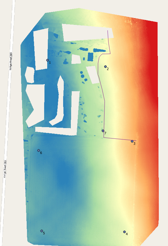
-1. Mark the ground control points, fly the site and survey (log coordinates) the ground control points.
-2. Post process using Emlid’s rtklib and process images with Pix4D.
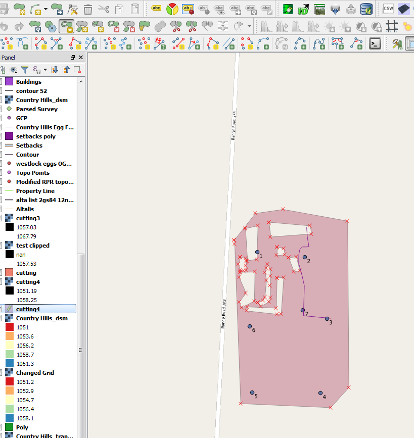
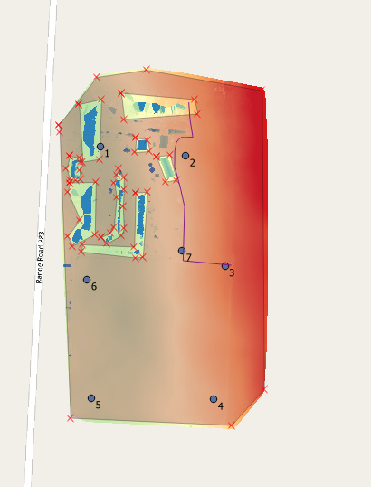
-3.Load the DEM and and orthomosaic into QGIS.
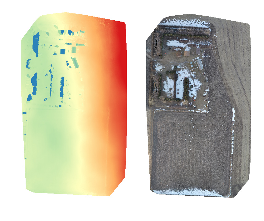
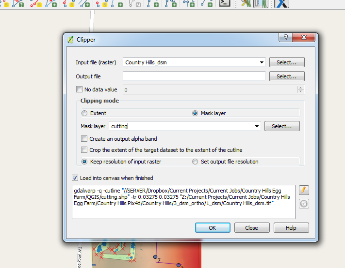
- The DEM will show buildings, trees, and other non topographical features. These can be removed in QGIS by just deleting around them using the raster clipping tool.
– Clip around trees, buildings, fence lines, machinery, etc.Part of my image had lots of trees so I made sure I only left DEM where I was confident it was the actual ground.
–
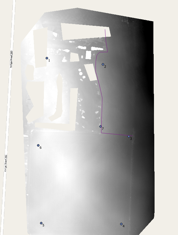
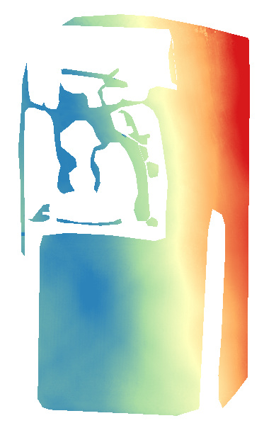
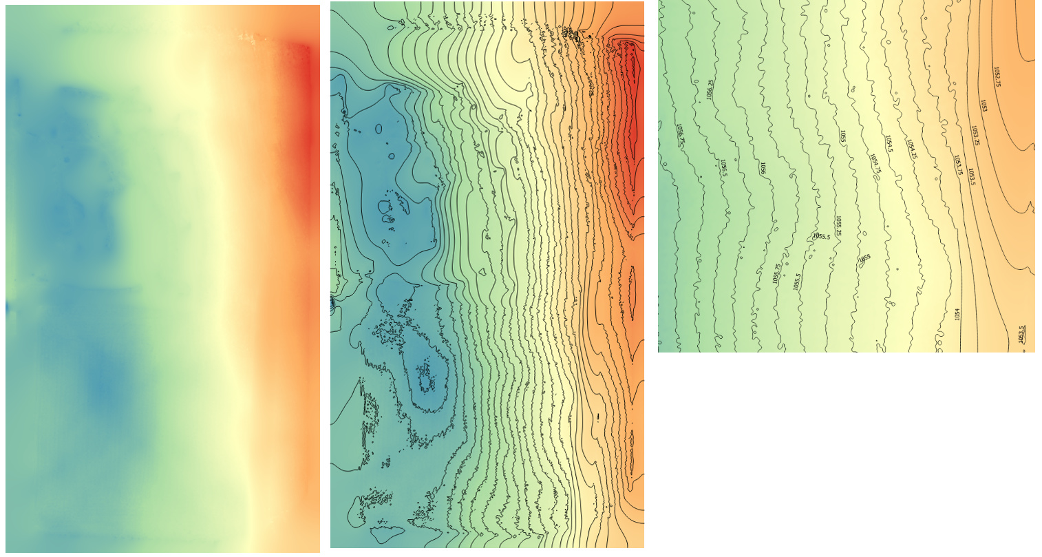
-In QGIS there are various tools for closing these gaps. I’m not sure which is the best. There is the grid tool(nearest neighbor), and the Saga Close Gaps tool.Using these tools you can create a new DEM, now technically a DSM, because all that is left is the topography.Mine isn’t perfect, but better.Close enough for what I need. Now you can use the Raster contour extraction tool to get actual topo contours.Turn on labels if you like.
–So far, these contour lines are just 2D lines with an elevation feature. We now need to convert them to actual 3d dxf contour lines. Then they can be used in Autocad, etc. but today we’re talking about Revit.
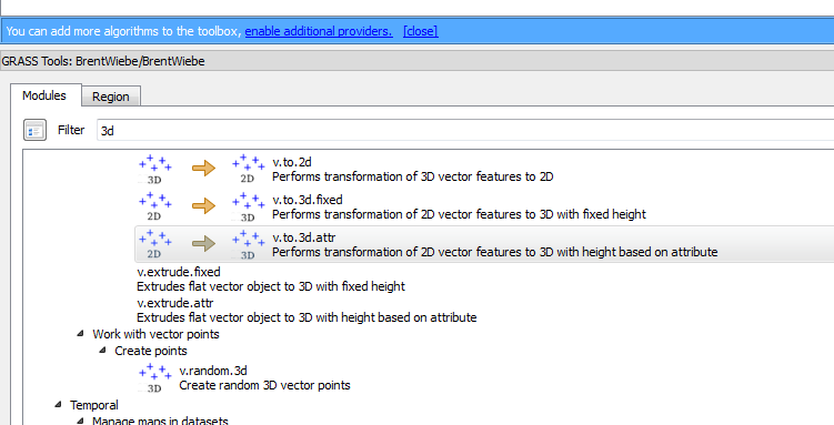
–Let’s search for 3D in the Grass Tools Toolbar in QGIS and use the following plugin.
The new contour lines can be exported as a .dxf file that we can use in Revit for creating the existing Topo.
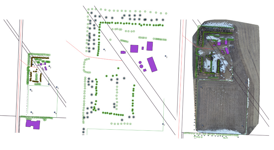
- Now let’s go back to our ortho in QGIS and save features, trees, fencelines, buildings, etc. We will load a georeferenced property line file as well. We’ll export all this as one dxf file for Revit as well.
- Now over to Revit.
Let’s link the Cad into a new site file. I won’t cover all the steps here… Revit users will be somewhat familiar with them. Basically, create a site and under manage coordinates, select “acquire coordinates” and click on the linked CAD file. This will apply real world coordinates to your Revit project.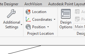
Now link your building project into your site project, position it correctly, and select “Publish Coordinates.” Now click on your linked Revit Project. You will be sending the coordinate system to it as well. When you open it you will find that its coordinate system has been updated.
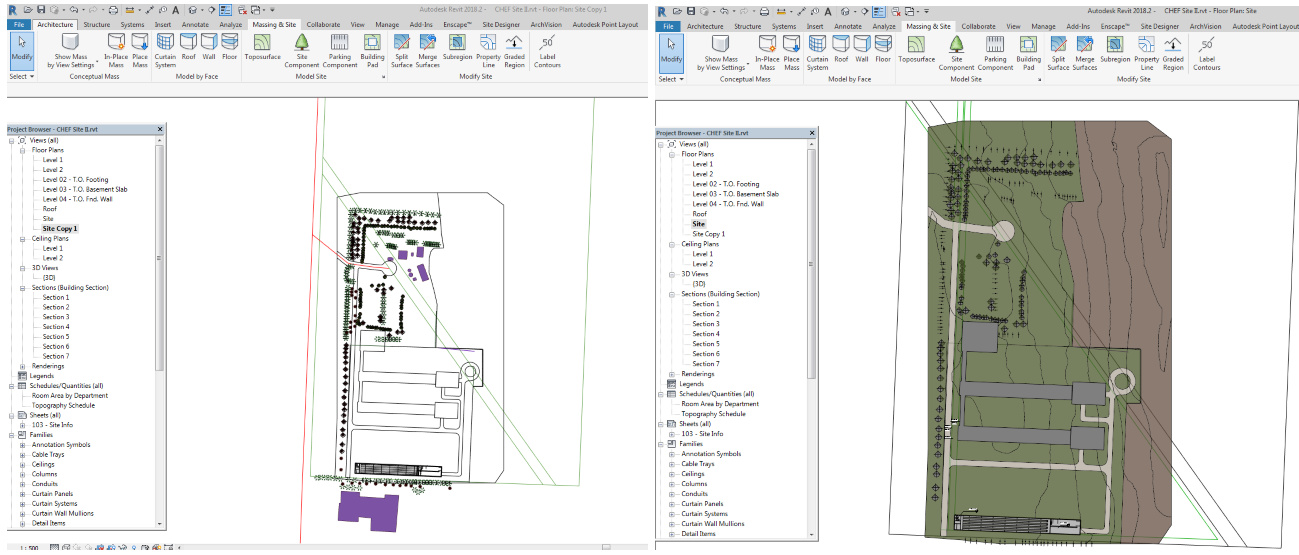
6. Next we need to create a topo in Revit. Under “Massing and Site” we’ll create a Topo.We’ll select, “Create from Import” and then click on our imported 3D Contour lines. Voila! We have a georeferenced topo in Revit! Now we can divide it into subregions, draw in fences, trees, and other features from our Cad file showing these things. We can also export from Revit and Import it back into QGIS if we want to work in there!
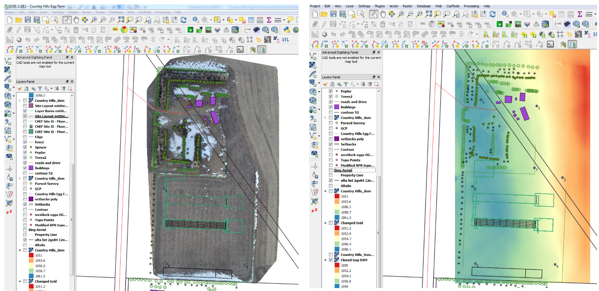
Because Revit can’t handle the orthomosaic we’ll go back to Qgis with the exported-from-Revit building footprint.
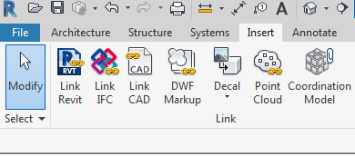
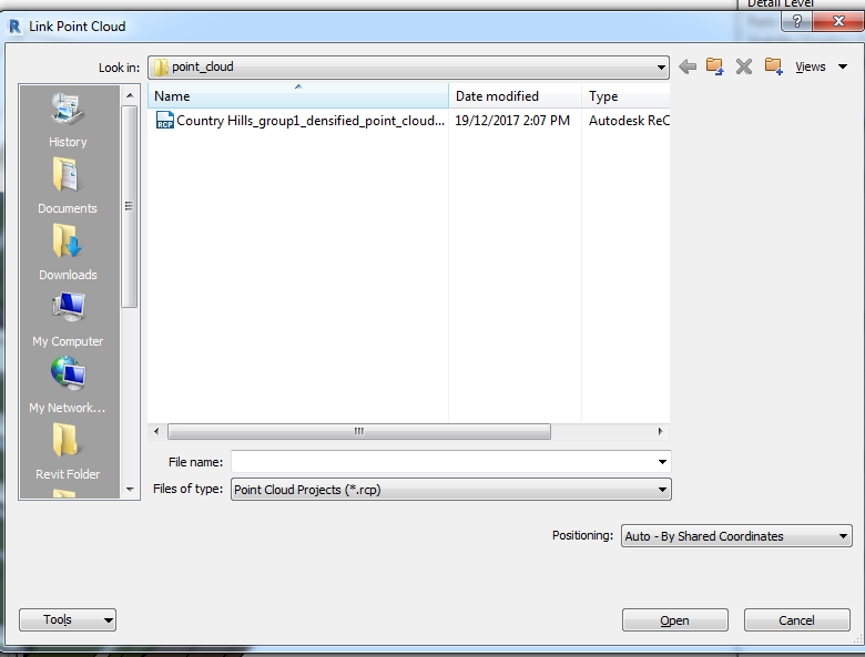
7. Now back to Revit. Remember, our project is georeferenced so we can import the point cloud from Pix4D straight into our Revit Project. This is straight forward. Select link Point Cloud from Revit and follow the directions! The important thing is to position it by selecting “Shared Coordinates”.
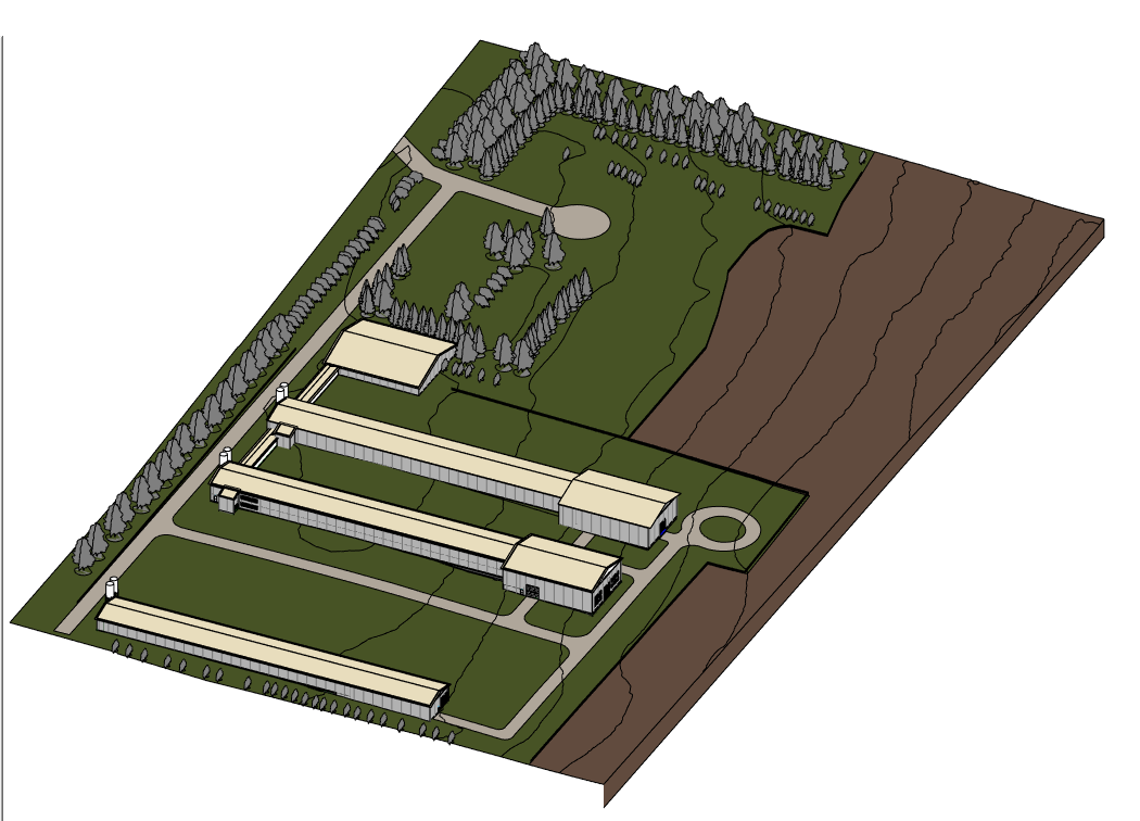
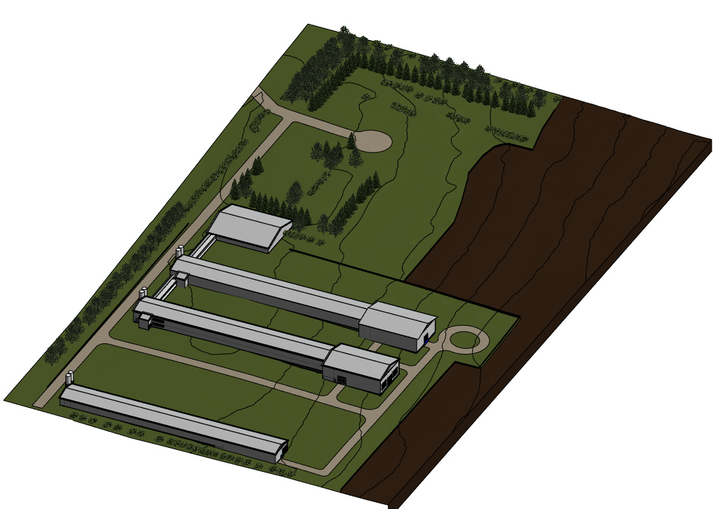
8. Now let’s have a look at what we have in Revit! The first two are not showing the point cloud. Point clouds cannot be used for anything other in Revit than a reference. Converting them to something else must be done in other software.
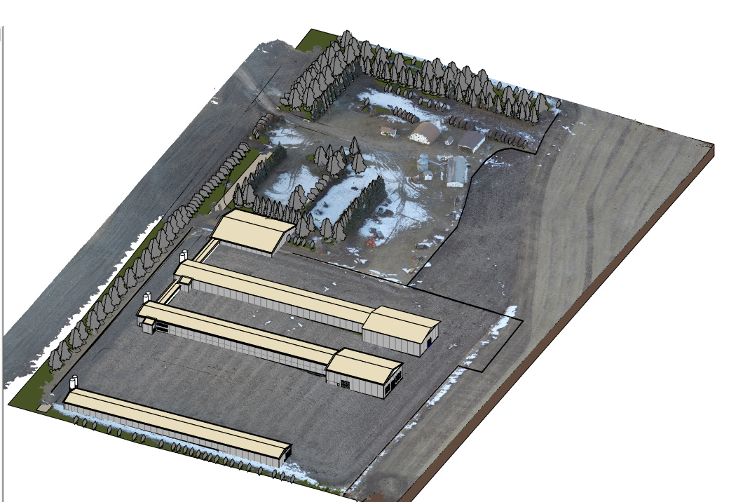
Here the point cloud is visible.
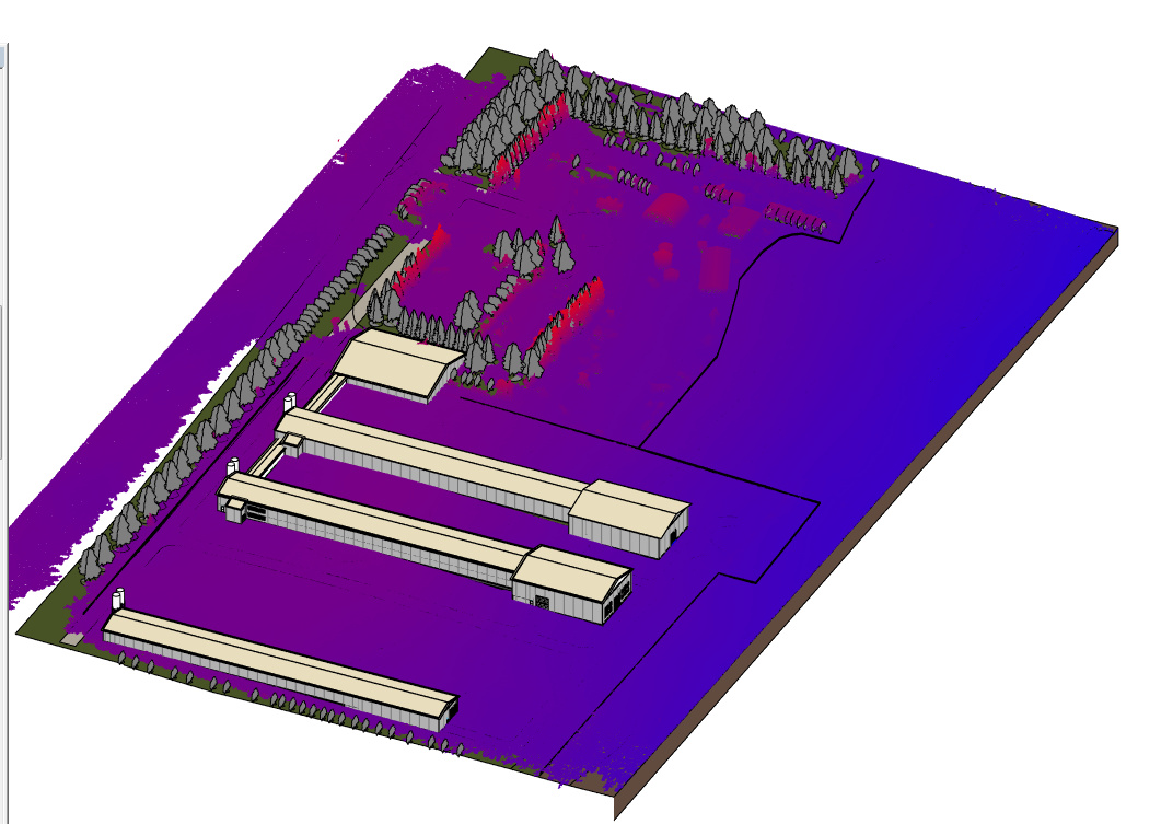
And here we can view the point cloud by elevation in Revit.
QGIS can import and export many formats and coordinate systems, while Revit is very limited, so from QGIS it can be sent to Autocad, Infraworks, and many more.
That is the end of this tutorial. Thanks for checking it out! ![]()