New Reach user here. For purposes of setting GCPs for drone flights, I’ve obtained and processed a RINEX file through OPUS but the OPUS Solution Report is still a bit of a mystery. I’m using a ground control point I set near the center of my project area as a base point and want to hold that point and its State Plane Coordinates as a fixed, firm reference point relative to all the other GCPs from which to scale the Reach-measured State Plane Coordinates (shot with a Reach Rover) for each GCP; and end up with a set of modified State Plane Coordinates or, basically, local coordinates with only the Base Point in actual SPCs. The project site is at an elevation of about 8,500’ (msl) and over a mile in length so the horizontal length in SPCs at sea level will be at least a couple of feet less than the ground surface horizontal distance at the project site.
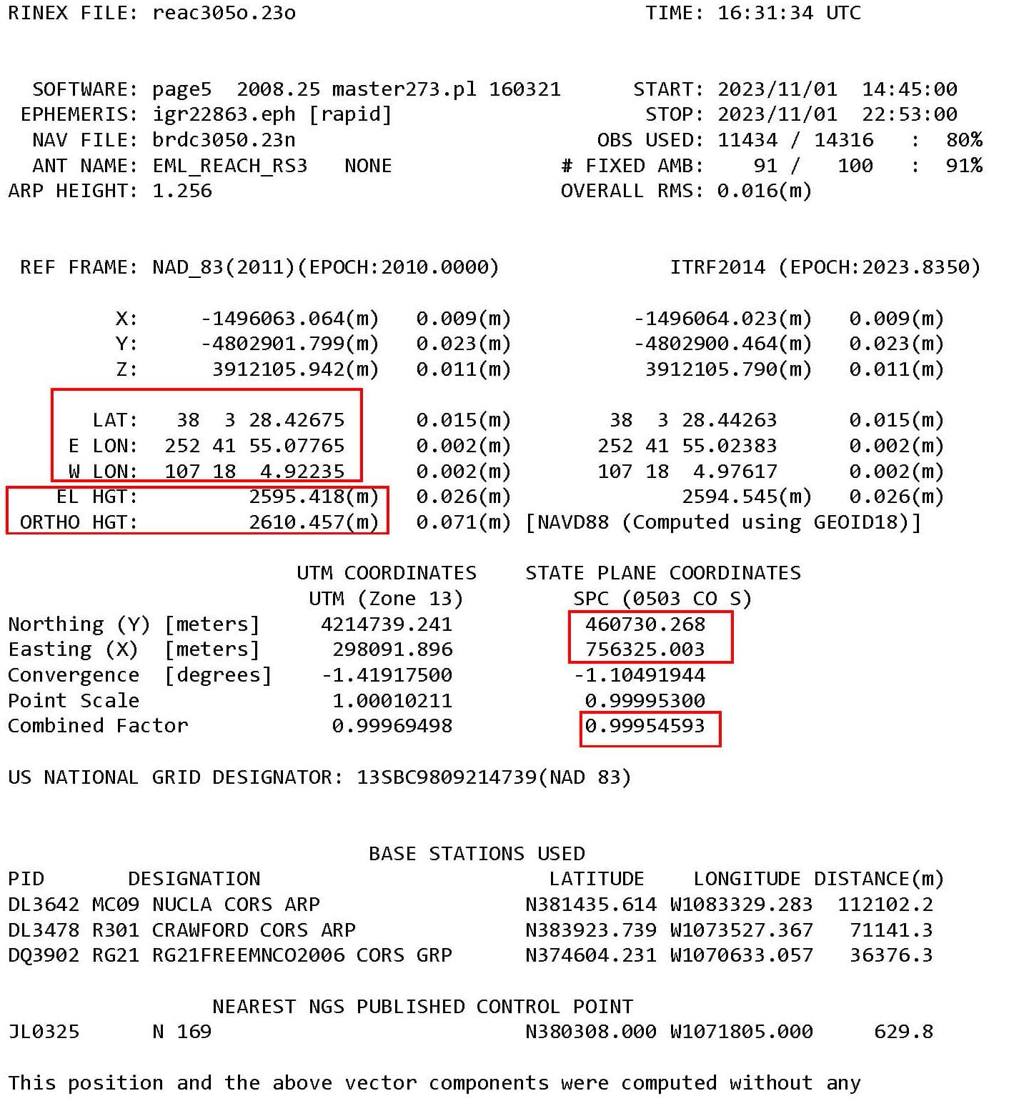
I had the Reach Base on the base point for about eight hours. I’m trying to determine which coordinates presented in the OPUS Solution Report are the coordinates that I should use as my corrected base point coordinates and which scaling factor (relative to the base point that is being held ) needs to be applied to the vector distances for the other ground control points shot with the Reach Rover. However, the Opus Solution Report contains several sets of coordinates and I’ve not been able to locate online a clear, concise description of how all these sets of coordinates relate to each and which I should use. There’s a ton of information online from NOAA and NGS but it gets way too deep into the weeds to clearly answer my questions. I’ve attached a jpg of the OPUS Solutions Report and highlighted what one person told me they “thought” I should use but they weren’t super confident in their answer so am hoping the Emlid Community could provide some clear direction. Thanks.
You’ve piled a lot of questions into one post. Lets start from here:
To be clear, you are setting up your base on an unknown point, and averaging for 8 hours, correct?
You then upload the file to OPUS and get a report, yes?
The coordinates on the OPUS report are the corrected coordinate in the various CRS; NAD83, ITRF2014, and State Plane. There isn’t any scaling that you need to worry about.
Thank you Dave! What I see on the OPUS report makes so much sense now. And, yes, I set up my Reach Base on an unknown point for eight hours and uploaded the Rinex file (created by the Reach receiver) to OPUS, and got a report back. In that report, I’m ultimately after the State Plane Coordinates values for my drone mapping GCPs.
The scaling I’m referring to is what is needed to horizontally adjust all my Ground Control Points, relative to my base point, to account for the high elevation I’m working at (typically about 8,500’ msl or higher). In the past, when I hired a surveyor to shoot my GCPs with GNSS, he would select a central base point within my project area to hold as a control with a true SPC, and then apply a horizontal scale factor to each GCP’s horizontal vector distance out from that central point. That would convert each GCP’s true State Place Coordinate x and y values (basically at sea level) to modified SPCs (at 8,564’) with only the central base point maintaining true SPC x and y values. I believe the surveyor used the “Combined Factor” under the State Plane Coordinates section of the OPUS report. The horizontal adjustment gets significant at higher elevations. A horizontal distance of 5,280’ on the Colorado South State Plane at sea level needs to become 5,282.48’ at 8,564’ msl. I’ve been going through some of my old projects trying to replicate what the surveyor did and am finally getting it figured out.
Historically I would have a surveyor do all this but surveyors are becoming more and more difficult to hire as they retire and few younger people become surveyors to fill in behind them. Last year and earlier this year I would have to wait a month or two (or longer) to get one on site. Often you don’t even get a return phone call on small tasks that don’t legally require a RPLS. From what I hear (from both surveyors and people needing surveyor work), this is a common and growing problem in many parts of the U.S. and State regulatory requirements are making it worse. Otherwise I would just continue to hire a surveyor. I’m thrilled and thankful that Emlid came out with the Reach to put the technology within reach of guys like me that can’t justify (and don’t need) a $70k RTK system with mm accuracy.
Steve. I don’t have any experience with the scaling to fit state plane at higher elevations that you are talking about. Others with such experience will hopefully jump in. Question. If, in the field, you do all of your work in LLH (which is probably what your are doing). Then in the office, you correct your base point with Opus (like you are doing) and then use Emlid Studio to use the corrected base to apply the correction to all of your GCPs. And after that, you then transform all of your GCPs to state plane, won’t any adjustment happen automatically rather than having to do the sorts of scaling your surveyor did?
It seems that the scaling requirement is because of jumping from LLH to state plane in the middle of the work rather that doing all the correction and then converting to state plane at the end? The surveyors workflow may have been the more complicated route, but I’m not sure it needs to be like that. Again, maybe others will jump in.
I agree with your observation with surveyors. At least here in Washington state, I think the way the surveyors association requires academics plus all kinds of nuanced internships makes it very difficult to actually become surveyors. They did it intentionally to control the market. But over time, it is killing the profession. Just my opinion.
I don’t mean to suck anyone into this GRID TO GROUND black hole… but 2 VERY KNOWLEDGEABLE registerred surveyors here that may be able to help a bit are @EBE111057 and @michaelL There are probably others here, but these 2 great guys really stand out
For us here in our region of SC (mid upstate) the grid or combined scale factor is minimal and really has no effect on grid vs ground distances. We have tied all our surveys from day one (1972) to the NSRS either using NAD27 or since changed to NAD83. For each boundary or construction site, we establish a fixed control mark that we show on our final survey maps or construction control diagrams. Our metadata contains the same data much like the standard OPUS report or NGS datasheet showing all pertinent data for that point, especially scale factor as well as combined factor.
The point is simply a reference mark or control point for our information shown so future users will know how to reestablish boundary corners or control marks for the site. All measurements shown from that point are true ground measurements.
You don’t mention what size of area you are surveying. You can simply pick a mid region of the site and apply the combined scale factor to all surrounding points if it’s a small project. Or if it’s a larger site you can use all points, average the combined scale factor and use throughout the site. Here’s a good explanation of the proper use of scale factors :
he would select a central base point within my project area to hold as a control with a true SPC, and then apply a horizontal scale factor to each GCP’s horizontal vector distance out from that central point
Ground and grid distances indeed differ depending on the surface height. But to find the GCPs coordinates with a GNSS unit, you don’t need distances or angles like in traditional surveying methods. So, it should be possible to collect GCPs with 2 Reach units without additional scaling. The heights you obtain will be calculated from the reference surface depending on the chosen vertical datum (ellipsoid or local geoid), and you can set the same vertical datum for further data processing.
I see a possible workflow as follows:
Add the Reach base position in Base Settings. You can use Lat, W Lon with a negative sign, and ellipsoidal height in NAD83(2011).
Create a new Emlid Flow project in your State Plane CS and a local vertical datum. The name of the CS should start with NAD83(2011).
Ensure the Rover unit receives the base corrections and calculates a Fix solution, and you’re ready to collect the points.
If I’m missing something, feel free to correct me!
Thank you ksenniia. Regarding your suggested workflow, and as it relates to Dave Pitman’s last reply and his question if the processing could all be done on the fly in Emlid Flow. For clarity, please note that I use the term “Corrected” to mean the GNSS error corrections provided by the Reach Base to the Reach Rover verses the terms “Adjusted” and/or “Modified” presented here to mean the adjustments typically made to State Plane Coordinate points collected with a Reach Rover (as opposed to a total station) at an elevation significantly higher than the Ellipsoid (e.g. many thousands of vertical feet or meters higher) , and needed to rescale the collected State Plane Coordinates grid distances to the actual ground surface distances. Again, this applies mostly to situations where state plane coordinate points are collected at high ground surface elevations. Near seal level, this whole discussion is pretty much moot.
Your three bullet points make sense to me; mostly. If I create the Emlid Flow project and specify State Plane Coordinates, and then proceed to collect points with the Rover (corrected on the fly to the Base station coordinates), do the final points stored in the Emlid Flow Survey CSV file have easting and northing grid values (e.g. as projected onto a flat plane located at the ellipsoid elevation and, therefore, still needing a scaled, horizontal adjustment eventually resulting in modified state plane coordinates) OR do the points stored in the Emlid Flow CSV file have easting and northing ground surface values as projected onto a flat plane at the elevation they were collected at such that no further adjustments are needed? If the latter is correct, I don’t understand how Emlid Flow would do those final adjustments without having a “Combined Factor” entered into Flow before collecting the points with the Rover. Thank you.
@SteveB , I have found with the introduction of Localisation, you can kind of work both ways.
If you operate without Localisation and require ground distances, you will need to calculate the ground distances after the fact, meaning it is Grid Projection.
If you operate with Localisation to ground distances (such as survey marks from traditional survey or survey plans), then the Easting/Northing basically takes the scaling into account, meaning Modified Grid Projection. For me, usually one of the points in the survey already have a published/adopted Grid Easting/Northing (which means everything is then kind of close) and Localisation basically makes everything fit, including Heights. The Easting/Northing can then just be site specific making importing new data into programs like AutoCAD much, much easier.
Thanks Joel. It’s really helpful to have this confirmation from you, and the others in the Emlid Community, on the workflow as an RTK newbie. Greatly appreciated. The veil is lifting for me as I understand more about the process.
The Localization feature has already proven itself a couple of times. I’ve been a total station user for about 30 years (I’m not a surveyor but do project-specific survey on my own work as needed and where a PLS is not legally required) so went out to a couple of my projects where I needed to find some control points set ten to fifteen+ years ago and used Localization on a few of the found points. Worked like a charm and came in dead on to those points. Pretty slick.
As a result of the Emlid Flow survey, you’ll get Eastings and Northings in the State Plane projection with no additional adjustments. The height is the distance to the actual ground point measured from the reference ellipsoid or geoid surface.
I agree with Joel – if you’d like to bring all the data to a locally determined CS, localization is a good solution. I’m glad to know you’ve got nice results with it on your tests!
I’m a little late to the conversation, but if you apply a scale factor then you are no longer on State Plane Coordinates, but on some localized ground coordinate system that could cause confusion if coordinates are very similar to the state plane coordinates and the differences between the two exceeds the tolerance of your project.
Our DOT would subtract a million from the northing values and maybe 1.5 million from the easting then apply the scale factor so the ground coordinates would have a noticeable difference from state plane coordinates