


Hello.
Tried to connect a couple of ESC’s today and ended up burning all four of them. (Still cant get why they burned).
Two of the four ESC’s where connected to motors and the last two wasn’t.
I even had the bad luck of burning one of the motors.
I’m now in the process trying to find out what the cause of this is.
Here is a description of the system:
1 Navio2 & Raspberry Pi 3.
- Linux navio 4.9.45-94f47ec-emlid-v7+ #4 SMP PREEMPT Wed Aug 30 18:17:43 MSK 2017 armv7l GNU/Linux
- emlidtool version: 1.0.3
- Test output (Connected to USB voltage during test):
WARNING Please check board voltage (4.215V)!
INFO pwm: Passed
INFO lsm9ds1: Passed
INFO ms5611: Passed
INFO rcio_status_alive: Passed
ERROR adc: Failed – Reason: Tramp
INFO mpu9250: Passed
INFO gps: Passed
– Edit –
(With battery connected instead)
INFO adc: Passed
INFO gps: Passed
INFO mpu9250: Passed
INFO pwm: Passed
INFO ms5611: Passed
INFO lsm9ds1: Passed
INFO rcio_status_alive: Passed
4 ESC 30A 2s-4s with built-in BECs Output 5v 2A
2 650KV motors
1 2200mAh 4s LIPO
Only kept the middle wire in one of the four ESC’s.
** EDIT **
As a friend pointed out to me, something that might be of interest is that the ESC with the BEC connected was the one that had a motor burning as well.
It only took about 2seconds for all of them to release the grey magic smoke.
I have checked that the ESC positive and negative was properly connected to the power distribution board.
I checked that GND was connected to the lower row and “signal” was the upper row. BEC output was disconnected as I mentioned earlier.
Will upload pictures of the gear and how the ESC were connected to the power supply board
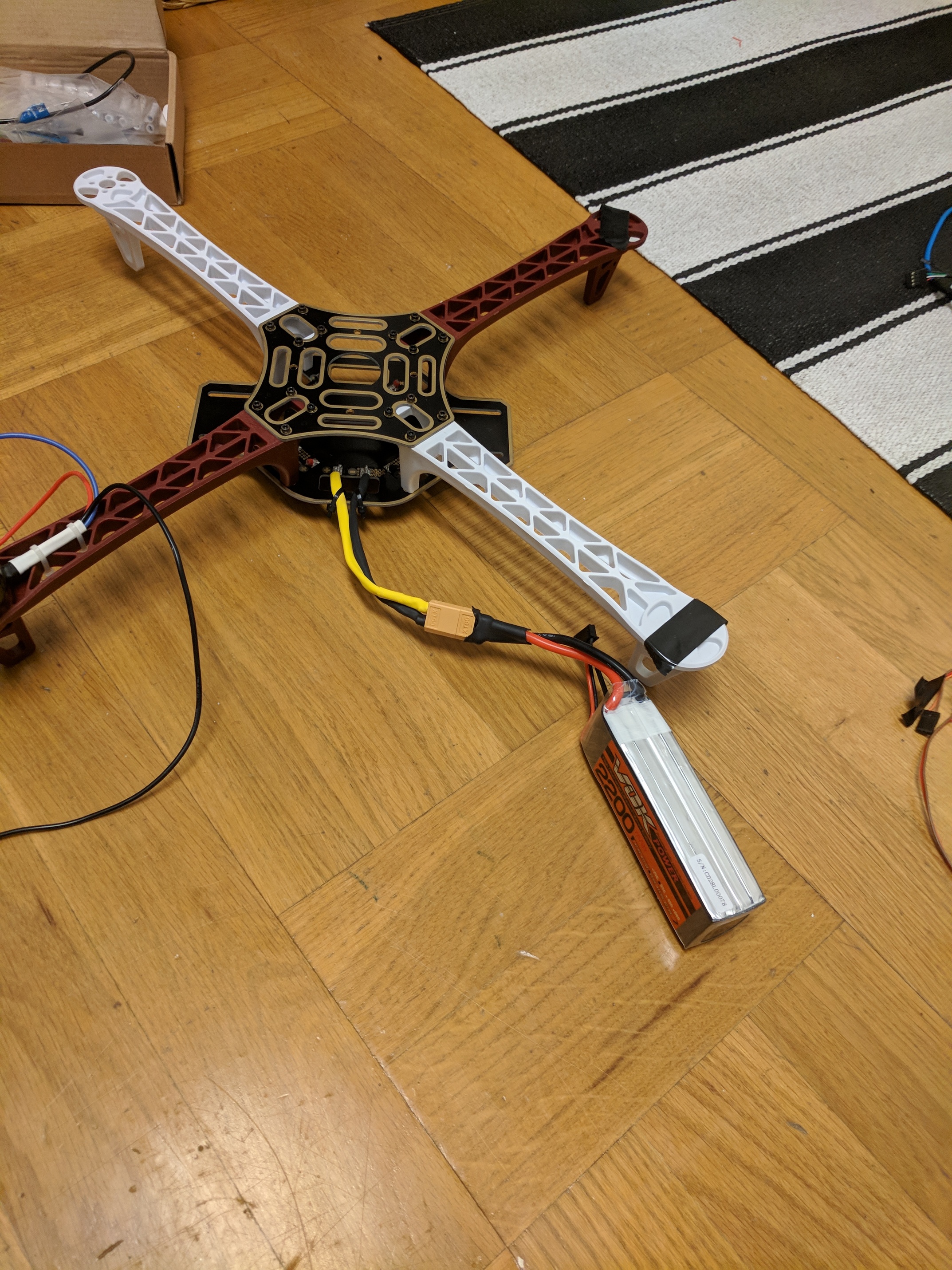
14.8V LIPO battery 4S type:

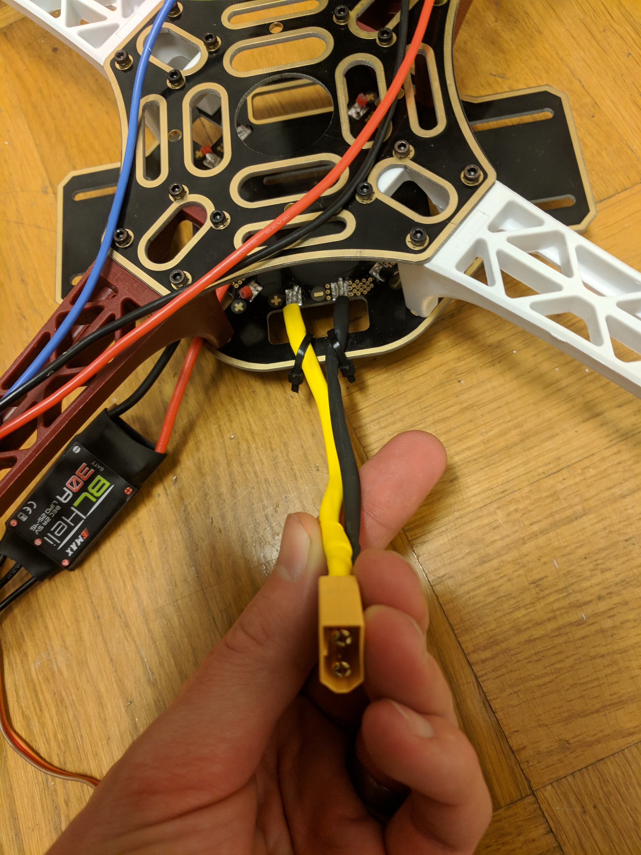
Just an overview with battery connected to the board. At the time of the incident the battery was connected to the Navio2 power supply module and the other end connected to the black and yellow cable:
Picture showing incoming power and how the ESC + was connected to the marked + (Note that I cut the cables after the incident)
You are able to see a remaining piece of the positive lead still fastened with solder:
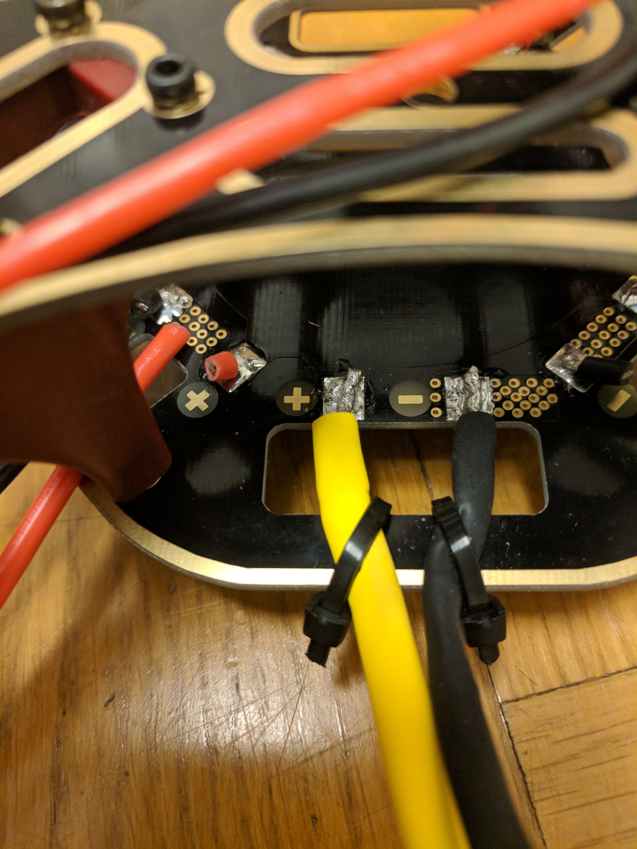
If I understand this correctly signal upper row and GND on the bottom:
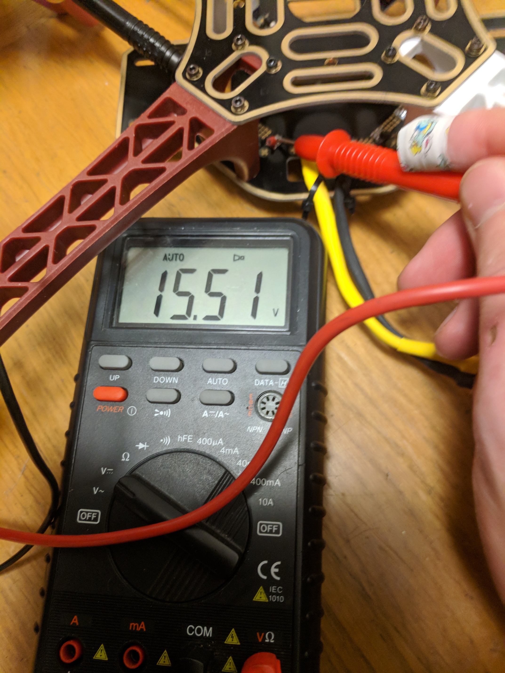
Volt measurement confirming correctness in polarity (unless I got a seg fault in the brain):
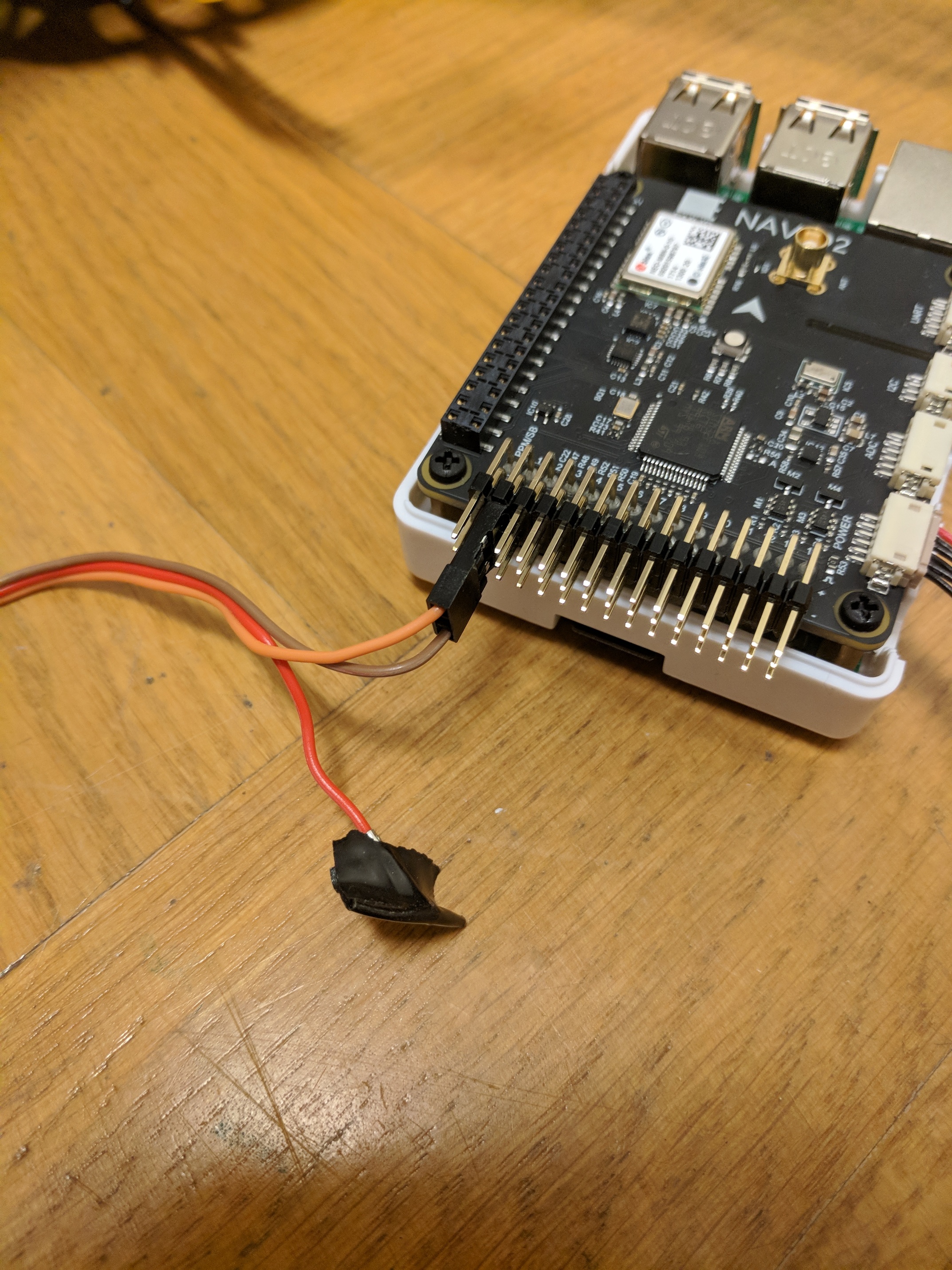
Picture showing connector to power supply board:
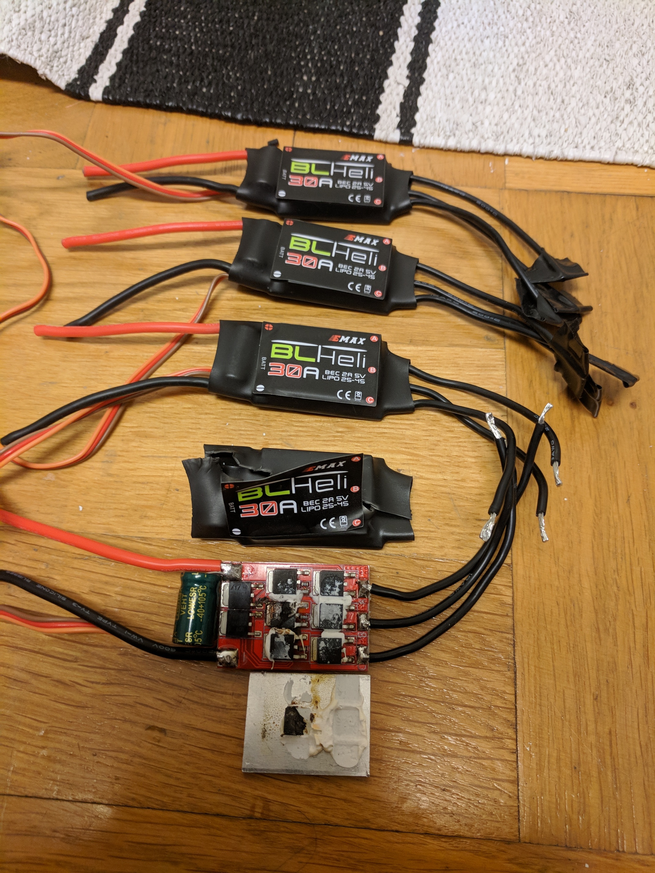
The mass grave:
I downloaded the “driver” and Python coding example trying to control the PWM outputs to check with a voltmeter what I get on the outputs.
When setting PWM_OUTPUT to 0,1,2,3 or 4 I noticed that all of them gets activated and outputs a signal noticeable by my voltmeter. If I set PWM_OUTPUT to 10, output 9 also gets activated but not 11.
Is this normal?
Anyone with recommendations on ESC’s that is known to work well?
Just to clarify, this post contains 3 questions:
- Any ideas to why my motor and 4 ESC’s went up in smoke? (Will add pictures shortly to help clarify)
- The PWM-outputs is behaving oddly, is this normal?
- ESC hardware recommendations?
UPDATE
From the responses I got to this question, much is pointing towards the ESC being faulty.
Possibly faulty firmware.
Lesson learned is to not have a motor connected when trying unknown ESC’s.
