Hello, someone tried the Navio + with Spektrum receiver without PPM encoder?
Thank
Hello, someone tried the Navio + with Spektrum receiver without PPM encoder?
Thank
Navio(+) only works with ppm input at the moment and only has one input connector. How would you connect a receiver with PWM outputs to it?
If you have a Spektrum TX, you could use OrangeRX receivers with ppm output.
Thank you for your response.
Spektrum uses no PPM output on the receiver?
Hello, APM 2.xx
spektrum the receiver does not use PPM encoder.
I’m not talking about Pixhawk that uses DSMX.
Thank, JS
Note that I have not yet received the Navio +
Hello, I come to understand that the Spektrum has no PPM output but,
it uses all the PWM output on APM 2.xx.
Thank you for your help, Jean-Seb
If you would like to use receiver without PPM output with Navio, you can use PPM Encoder:
https://store.3drobotics.com/products/ppm-encoder
I have just got my Navio+ and I have got it to work with my old Spektrum PWM reciever. It needs some simple electronics (4 diodes, a resistor and a transistor) and a few changes to the Navio ArduPilot sourcecode (RCInput.cpp and RCInput_Navio.cpp) before rebuilding ArduCopter. Some of the channels needed reversing in the transmitter - I had to find the book to remind myself how to do that!
If I get the confidence that it works reliably I will post the details here.
Hello and thank you, I will follow with interest your progress.
Thanks for your interest.
Here goes…!
I bought my Spektrum DX7  and AR7000
  in 2008.
I don’t know if all DX7s are the same as mine, but this approach worked for me with UAVP in 2008 - see [here][1]
 This is the circuit that converts the 7 PWM outputs of the AR7000 into a single signal where the time between successive transitions is the PWM value of each channel. See in the above picture of the receiver how I mounted the circuit directly on the PWM plugs, so no need for lots of PWM cables.
The stock version of ArduCopter is expecting a series of PPM signals, where the time between positive going transitions is the PWM value of each channel.
I followed the instructions [here][2] to download and compile the navio branch of ArduCopter with the following changes:
In libraries/AP_HAL_Linux/RCInput_Navio.cpp replace LinuxRCInput_Navio::_timer_tick() with:
void LinuxRCInput_Navio::_timer_tick()
{
    while (true) {
        int bytesAvailable;
        ioctl(pigpio, FIONREAD, &bytesAvailable);

        if (bytesAvailable >= 12)
            ::read(pigpio, reinterpret_cast(&gpioReport), 12);
        else
            break;

        prevtick = curtick;
        curtick = gpioReport.tick;

        width_s1 = curtick - prevtick;
//            fprintf(stdout,"pulse %i\n", width_s1);
        width_s0 = 0;
        _process_rc_pulse(width_s0, width_s1);

    }
And to map the channels correctly, add to libraries/AP_HAL_Linux/RCInput.h:
uint8_t _pwm_map[LINUX_RC_INPUT_NUM_CHANNELS];
and modify libraries/AP_HAL_Linux/RCInput.cpp:
LinuxRCInput::LinuxRCInput() :
    new_rc_input(false)
{
    ppm_state._channel_counter = -1;
    for (uint8_t i = 0; i < LINUX_RC_INPUT_NUM_CHANNELS; i++) {
       _pwm_map[i] = i;
    }
     _pwm_map[0] = 0;
     _pwm_map[1] = 4;
     _pwm_map[2] = 6;
     _pwm_map[3] = 1;
     _pwm_map[4] = 5;
     _pwm_map[5] = 2;
     _pwm_map[6] = 3;
}
and change both occurence of this in libraries/AP_HAL_Linux/RCInput.cpp:
_pwm_values[_pwm_map[i]] = ppm_state._pulse_capt[i];
Some of the channels had the wrong sign and I had to find the book for the transmitter to find out how to invert them. To test it, I just used the RC calibrate section of APM Ground Station.
I hope this helps someone. As always, YMMV!
[1]: http://www.12thechilterns.eclipse.co.uk/
[2]: http://docs.emlid.com/Navio-APM/building-from-sources/
Hi, I find your work very interesting and well done.
I think many people will use it.
Jean-Sebas
I have a Spektrum DX7s with an AR8000 receiver and followed the steps of changing and compiling the code. Then I soldered 4 diodes/2 resistors/1 transistor as described.
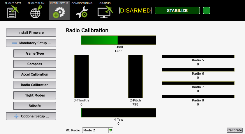
Unfortunately the Radio Calibration in APM Planner v2.0.17 only shows the channels 1-Roll and 2-Pitch being active. The other channels remain black/inactive.
The AR8000 has one more channel than the AR7000, so I thought there is a chance to get this working.
@martin Yes, I would hope that it would work as well. Sorry I don’t have an AR8000 to try but if you uncomment the fprintf in LinuxRCInput_Navio::_timer_tick() so that it reads:
        width_s1 = curtick - prevtick;
        fprintf(stdout,"pulse %i\n", width_s1);
        width_s0 = 0;
and recompile, you might be able to work out what is going on by looking at the printout on the terminal where you launched ArduCopter. You may have to change the PWM channels that the diodes use, and possibly add a 5th diode. Once you get 8 numbers (times in microseconds) that can all be changed by the transmitter, you can then change the _pwm_map to put them all in the right order. Oh, and you will have to add the 8th one to the map:
     _pwm_map[0] = 0;
     _pwm_map[1] = 4;
     _pwm_map[2] = 6;
     _pwm_map[3] = 1;
     _pwm_map[4] = 5;
     _pwm_map[5] = 2;
     _pwm_map[6] = 3;
     _pwm_map[7] = 7;
Sorry I can’t be more helpful without an AR8000. You could try googling for somebody who has already worked it out?
Please let me know how it goes.
It turns out that the Spektrum AR8000 receiver has overlapping channels in the PWM output, so I would need a PPM encoder.
Ah! That would explain why it doesn’t work. Shame really.
As per my observation the Navio can only works best with ppm input at the moment and also it has one input connector.
You must made some changes using the electronics and also some changes in the sourcecode of its .cpp file.
Because some channels needs the reverse in the transmitters.