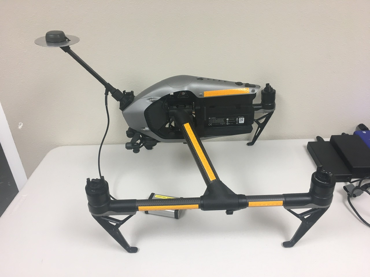
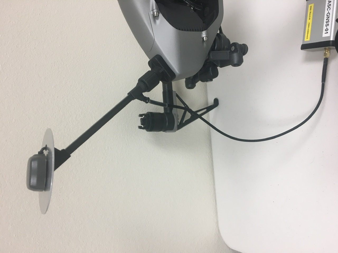
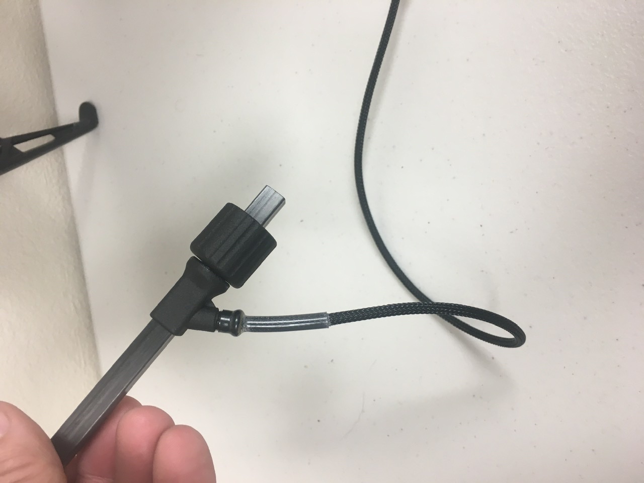
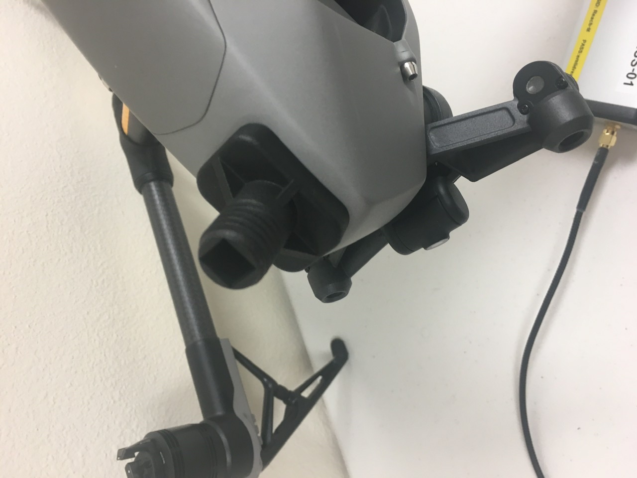
Hi all, I thought I would share my PPK system I am building for an Inspire 2. The antenna is a combination of 3D printed parts and carbon fiber tube. It screws on to the base for easy removal.
I have not finished designing the housing for the reach module yet. Currently I have it packaged in an aluminum project box. I added a lithium ion battery and small BMS to power it. I am thinking of adding an IMU and microprocessor to log and process dynamic offsets from the antenna to the lens, but I am not sure yet how much that will actually improve the precision and accuracy of a photogrammetry dataset.
My next steps are to take apart the x4s camera and figure out triggering. I will keep everyone posted if you are interested.
Impressive build, but looks like it is going to need some pretty detailed measuring and allot of offsetting. Is there a reason you didn’t angle it the other direction to go under the props towards the center?
Thanks Michael. I angled it forward to keep it from blocking the Inspires internal gps antenna. The extra length is to place it above the rotors. I was hoping to reduce multi path errors by doing this. Maybe it is overkill, I am not sure.
The offset from the antenna to the camera gimbal center in the drones frame is not too tough since I have it modeled CAD. My thought was to then use an AHRS(vectornav) to apply HPR data and reduce this to the camera frame, then it should be a static offset from the gimbal to the focal point of the lens. Anyway, I really don’t know how much that will improve the data, but I think it is worth playing with.
I was sure you had your reasons. I have a Phantom 4 Pro and a Yuneec H520 and in my experience with these and surveying GNSS systems there isn’t any interference between antennas. Your concern is probably most blocking of the internal module, but keep in mind that 99% of the satellites are going to be seen at an oblique angle. You already have a base plane so there’s no issue with multi-path from the drone itself. Both of my units are literally 4-inches above the onboard GPS and I see zero effects on either GNSS system of either bird.
It’s good that you have CAD because you will need to account for the tilt of the drone in flight when calculating your offsets and make sure that it is not taking pictures in corners or states of extreme acceleration and deceleration. Normally between 15-20 degrees with my drones, but I am sure there is info out there for the Inspires.
Very beautiful construction! How much weight will it add?
How do you sync the images and the position information?
I would test if you will have vibrations under windy conditions. Our experience is that a helix antenna with some vibration dampening gives far better results than the stock patch antenna.
If you are ready to donate something to the Against Malaria Foundation I would offer you to adapt my lever arm correction script for youre case (to use the attitude information stored within the images to correct the offset between camera an antenna). The script is already in productive use by another user and myself and has been tested successfully for accuracy against different tools.


 I have a Phantom 4 Pro and a Yuneec H520 and in my experience with these and surveying GNSS systems there isn’t any interference between antennas. Your concern is probably most blocking of the internal module, but keep in mind that 99% of the satellites are going to be seen at an oblique angle. You already have a base plane so there’s no issue with multi-path from the drone itself. Both of my units are literally 4-inches above the onboard GPS and I see zero effects on either GNSS system of either bird.