Hi I am currently integrating a Reach module into our pixhawk multirotor that we use for wall mapping. I am using a cable from the tuffwing guys that gets power from the pixhawk and connects to the Reach and the hotshoe on our Sony Alpha A 6000. We are looking to post process the raw logs from the Reach for each time marker from the camera hotshoe with the raw logs from our Topcon GR3 base station setup logging Rinex. I am not looking for RTK to inject back into Mission Planner as the real time position doesn’t concern us we are more interested in PPK.
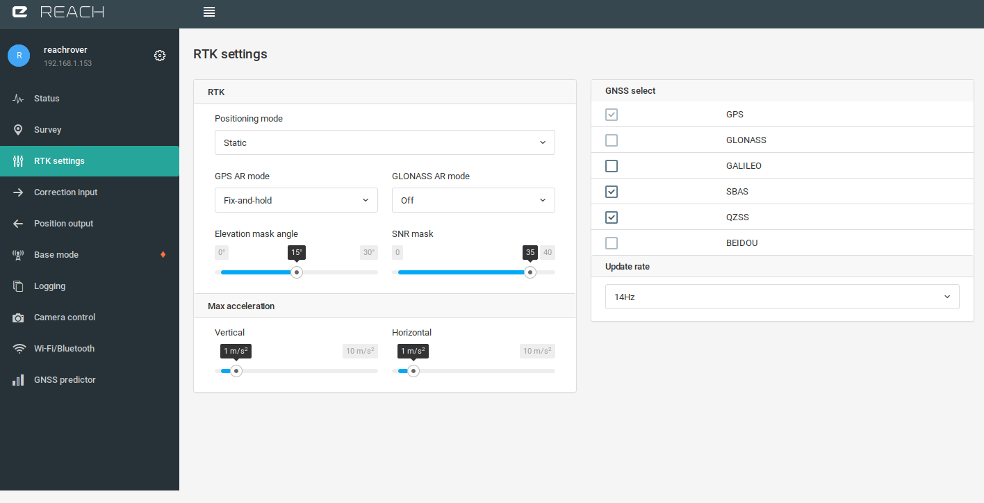
What setting should I be setting through Reachview for the Reach module to log those raw camera positions ?
Any help is appreciated.
So you are saying to just log GPS constellation on the rover as you can do so at a higher HZ rate that will better match my L1/L2 base station ? Given that the rover will be on the UAV and constantly moving what other settings need to be on or off ?
Also what sort of initialization time would you recommend before sending the UAV on its autonomous mission ?
Do you need accurat movment or accurat coordinates from the UAV?
For accurat movement, like formations flying etc, you need RTK.
If you just gonna fly around taking pictures of god knows what, and need accurate (relative or absolute) coordinates to apply those images, RTK is not needed. Enable RAW logging, thats the only think you need to do on your UAV.
For postprocess, you also need to logg data from a reference station in the same time period. This could be your base, a vrs, cors etc… You need these data to correct the data from UAV.
Now, how you go about applying coordinates to a photo, there are some settings you could use in reachview, but i dont know much about that.
Hope this clearify things
We are not interested in RTK - too many issues around the radios. We are surveyors and run RTK survey accurate rover systems and have enough issues with those. PPK is better suited to our needs - we have no problem with the post processing and getting accurate base station data is not a problem all of our site base stations log static data and can output RINEX. I am more chasing the settings that I need to program into the Reach to ensure that it is logging the positions of the photo centres.
@Sylvain_POULAIN Thanks for that - Are you using these settings on a UAV to collect data for PPK processing ? I notice that you have set the GPS AR mode to Fix and Hold and not Continuous ? Does this provide a more effective solution for UAV PPK ?
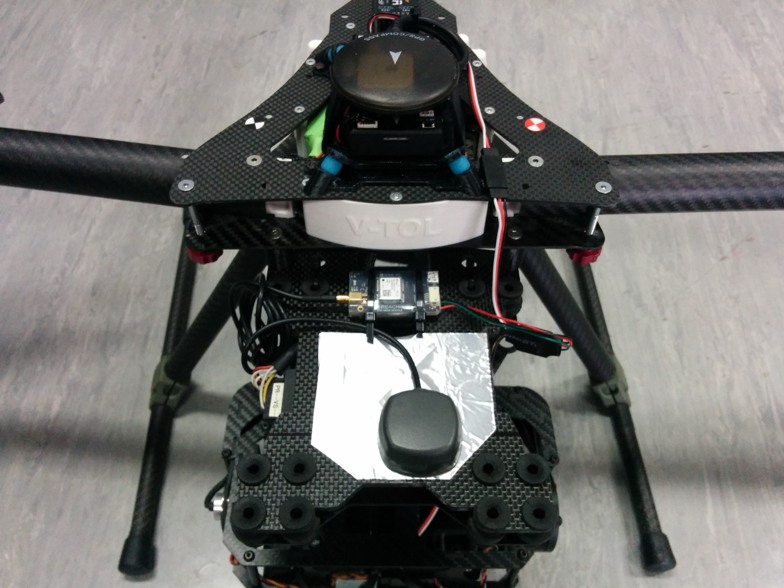
I see you have a secong gps. For backup?
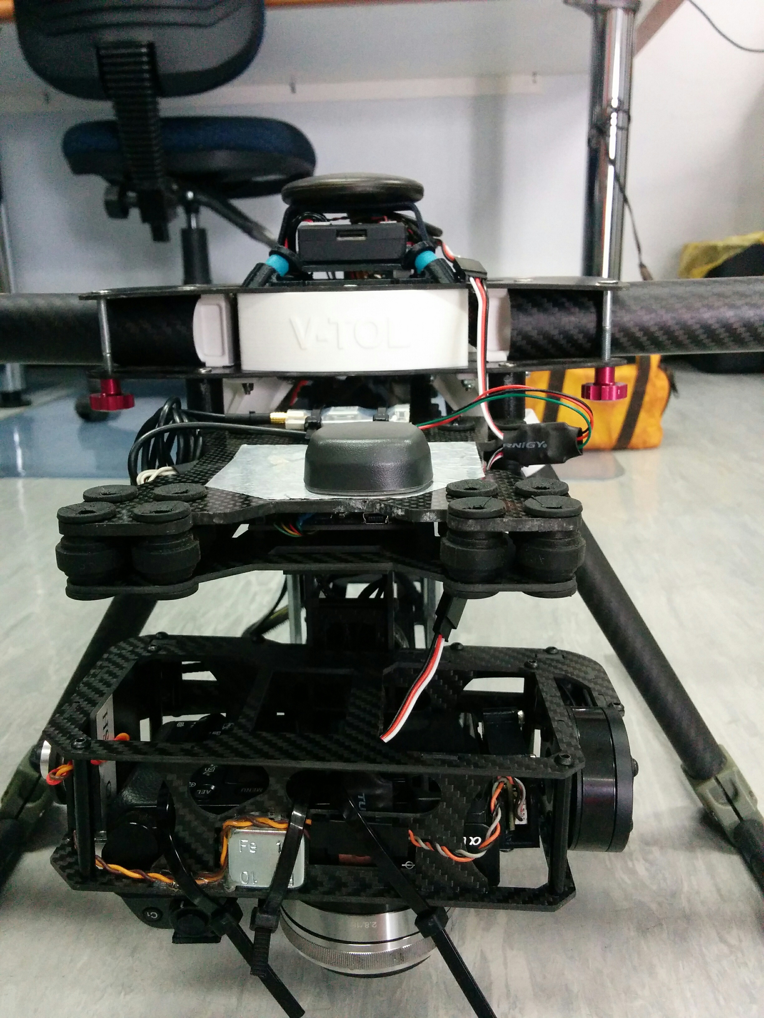
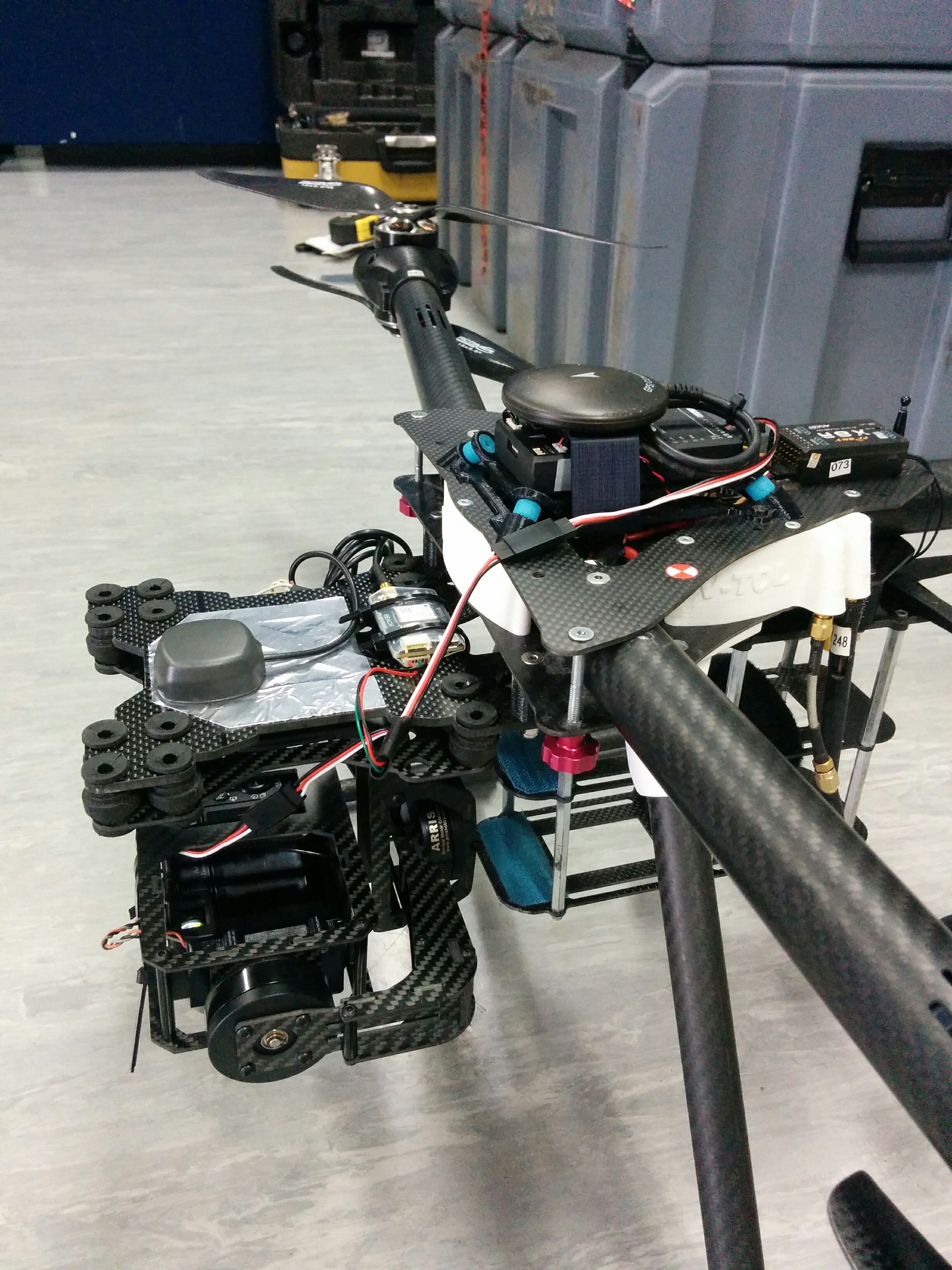
Where reach is place, there is a great chance of multipath, noice and some of the skyview back is blocked.
Right noe i dont think reach is gonna perform as intended. Reach need to be at the hight point on this copter
GPS AR does nothing for ppk. Everything is doing in post production.
I think your ground plane is not good. Antenna should be in center like this : https://docs.emlid.com/reach/antenna-placement/
Thanks everyone for the replies. We are going to raise the Reach antenna above the body line for the next flight - maybe even try a helix GNSS antenna to see if that improves the result. The other antenna is the Pixhawk GPS antenna just used for nav purposes not interested in touching it as it works fine.
The antenna was positioned on the ground plane like that to be centered over the cameras sensor as much as possible so that we just had a vertical offset to the sensor and no x,y.
Has anyone tried a helix type gnss antenna with the reach ?
Hi everyone just thought I would share some of the data from the test flights that we did with our pixhawk base multi copter and the reach. We had two Topcon GR3 base stations running collecting static data at both 1 sec epochs and 30 sec epochs ( Raw data files are attached). We processed one of the positions through AUSPOS to get a GDA94 grid coord for it as we had used a total station and traversed around some ground control so that we could run a base case using GCP’s only to compare to the PPK outcome of the Reach event positions. All the data was processed using Agisoft and the points clouds were exported to Maptek ISite Studio for comparison ( Terrestrial lase scanning software). Comparing the GCP point cloud and PPK derived position cloud we are getting a diff of around 3.8m !! I have included all the raw data if someone wants to see if they can derive me some accurate photo centres that might be better than what I have done ?
I have checked the base station position for both bases and have tried them both but the 30 sec epoch cannot get enough fixed event positions. The height of both base positions was calculated using the measured height and an ARP calc spreadsheet for Topcon GR3 to give the vert measured height to the ARP. I have attached the AUSPOS output so that both base stations can be used : 9000 is the 30 sec epoch base station and 9001 is the 1 sec epoch base station.
In the meantime we have ordered a Maxtena helical antenna and will position this on a GNSS antenna stalk about 120mm above the frame shown in the above photos - will post more once we get some field results. Emlid trial data
I have done this exact process before however I used an L1/L2 receiver. I found even with camera control points I needed at least 2 points on the wall to fix the focal depth in Agisoft.