Power Supply for Navio +, Reach, and Motors

Hello all!
At the moment, I have one big issue. The Navio+ can only take 4S batteries, however, most motors that I need (or at least, want) take 6s, 7s, or 8s batteries. Should I just use a 4s battery, or can I find a way to sort out the voltage so that the Navio+ doesn’t fry? (As in, voltage step down going into the Navio+ and then a Voltage step up when coming out of the Navio+)

Thank you!

The Navio+ itself does only take 5V, the power module bundled with the Navio+ maybe rated for 4s max, but you are free to use a BEC to power the Navio+, that can handle 8s lipos. Or you buy a high voltage power module like this one:

Thank you! I’m just curious, does the Raspberry Pi get powered through the Navio+?

Rather than an in-line power module, a Pixhawk/Navio compatible PDB may suit your needs:

Depends on how you planned to wire-up your ESCs, if you wanted a PDB or not. It may help tidy things up.

Power to the Navio is supported via 3 different sources and yes both the RasPi and Navio are powered regardless which way you go:

  1. Navio/Pixhawk power connector.
  2. ESC BEC output via any ONE servo cable.
  3. Raspberry Pi micro-USB power input.

The only restrictions to this “triple redundancy” are:

  1. You can’t connect more than one ESC power line to the servo rail else you may overpower the Navio.
  2. The radio receiver/RC-IN servo connector is NOT powered by the Navio or RasPi, because unlike the Pixhawk the entire servo rail is isolated in that direction (power out).
1 Like

I’d probably feed it through the Navio+, that way the motors are connected to the main power source (In this case, a 4S battery) Or is that wrong? (Basically what I’m asking is, how are the motors connected to the Navio+ and what is involved in connecting them together?)

ESCs take power direct from the battery (usually via red/black banana plugs) at higher power (full battery voltage/amperage) to spin the motors. Separately, they receive control signals via a 3 pin servo style connector, with two or three of the wires connected…

Additionally ESCs with integrated BECs send out 5v power as a convenience (down the servo cable red wire), e.g. for planes so you only have one power line through the motor ESC then to the flight controller. But on multi-rotors we then have too many. So disconnect and tape-up the power line from all but one of your ESCs.

If you have “opto” ESCs they ditch the BEC altogether, and if they are truly “opto” (not just missing a BEC) they also electronically isolate the two (high and low) power circuits better, which helps avoid sending interference back to the flight controller. But then you need 5v at least for the RC input, but maybe for Navio and any other servos you want.

So why bother with a separate Navio power source? Because you really need to know the battery voltage so you can land before it drops out of the sky. For this the normal way would be to use the Navio power connector with Pixhawk compatible module, as Emlid sell too, or a PDB like the one I suggested.

And why a PDB? Normally you would have to splice the battery wires out to each ESC/motor, which could get messy. The PDB with APM/Pixhawk voltage & amp sensor integrate gives you the best of both worlds, tidy-up your ESC supply and also give the necessary information to Navio/APM.

Furthermore, the one I linked to also provides two additional separate 12v and 5v power supplies. That’s perfect for me because I power my Mobius from the one (5v) and my OSD and Video transmitter (12v) from the other. The power is also clean (on that model) so it saves adding low pass filters to get rid of video interference.

I use that PDB all the time, it’s good for 10 cell batteries. But as I only need 4s next time I would get the new Hobby King “micro” PDB module they recently released.

The connections are documented here:

http://docs.emlid.com/Navio-APM/hardware-setup-navio-plus/

Only point of caution on the diagrams there, is it shows red wires from all the ESCs. Remember only one power input should be connected to the servo rail.

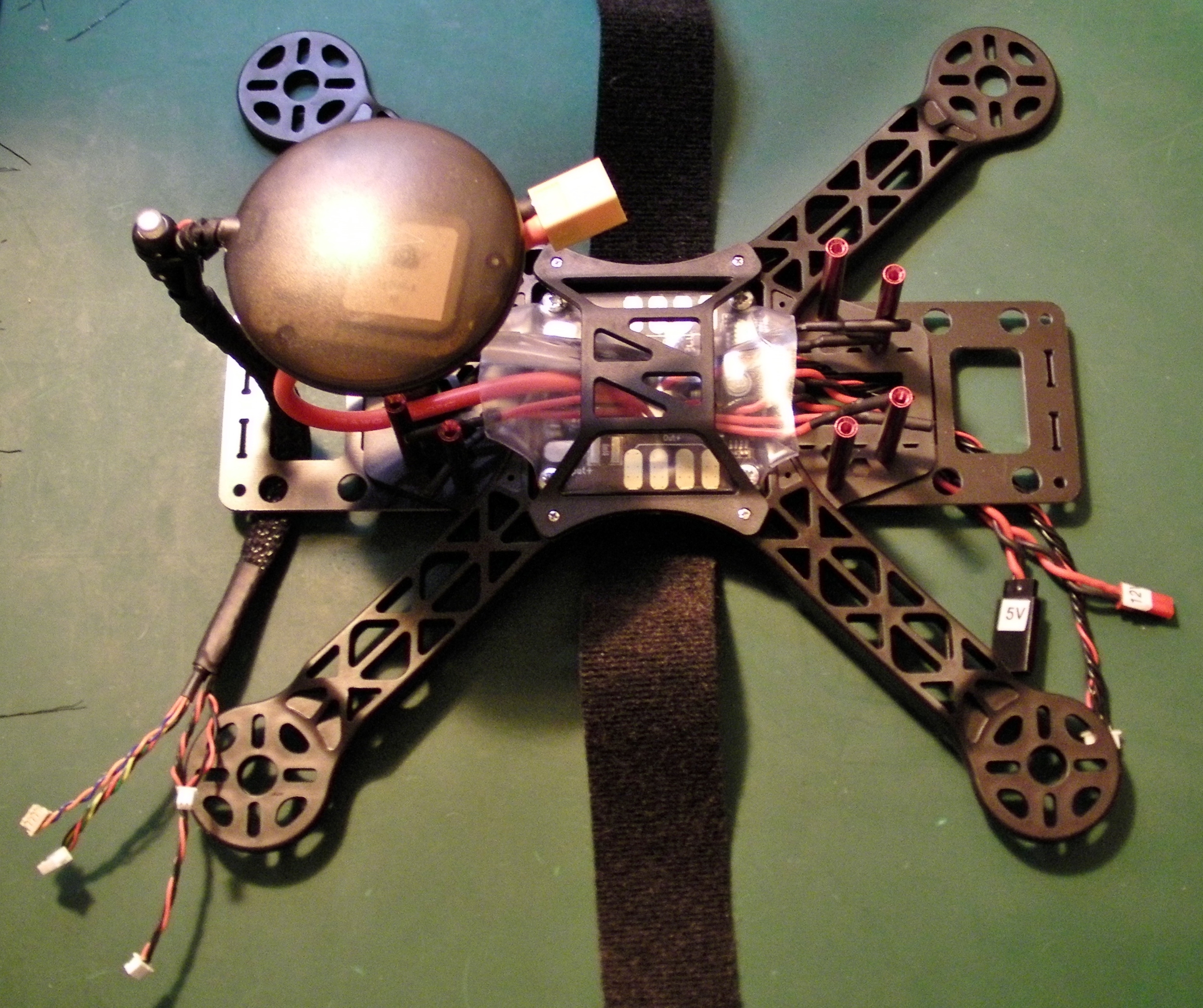
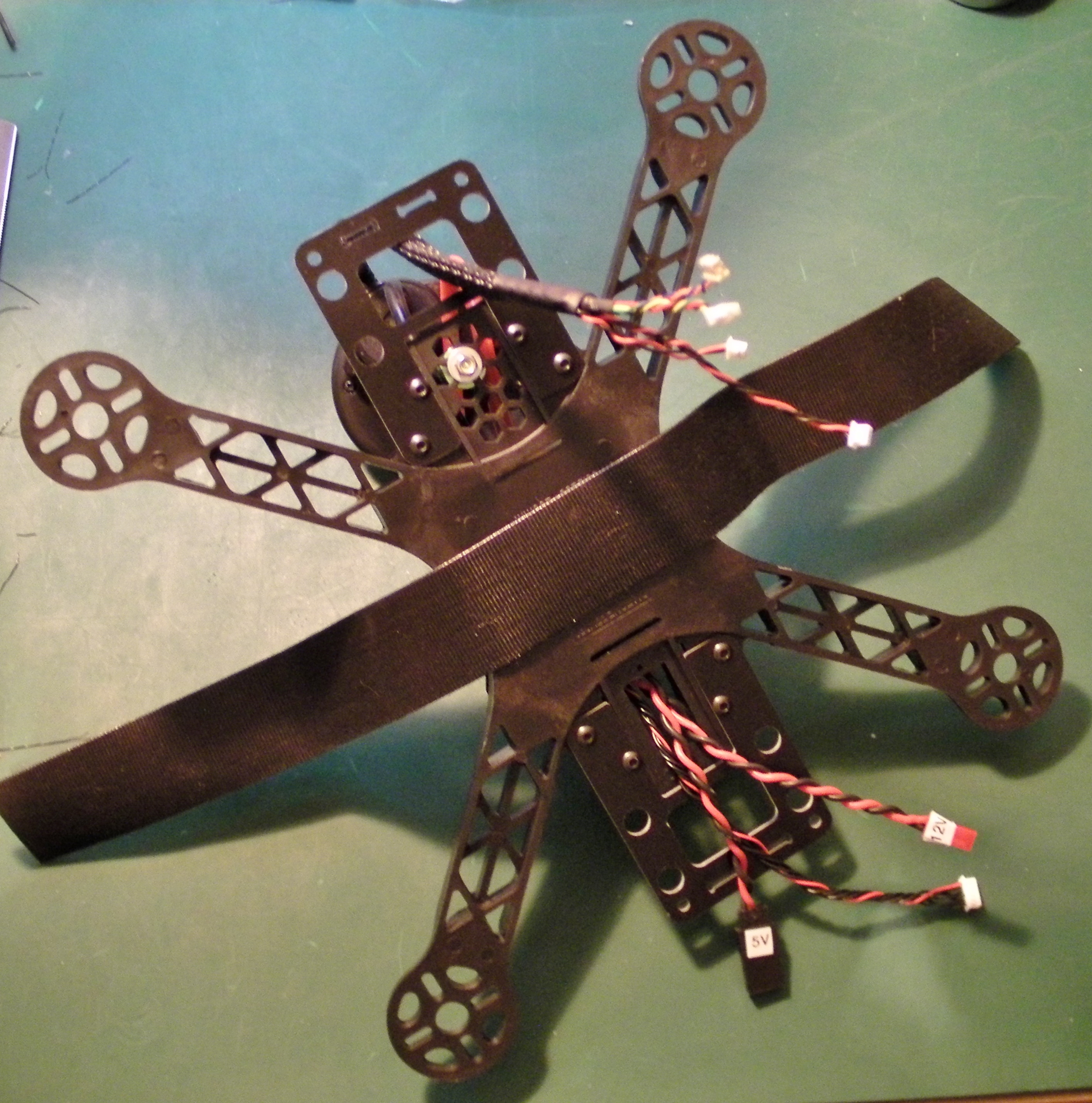
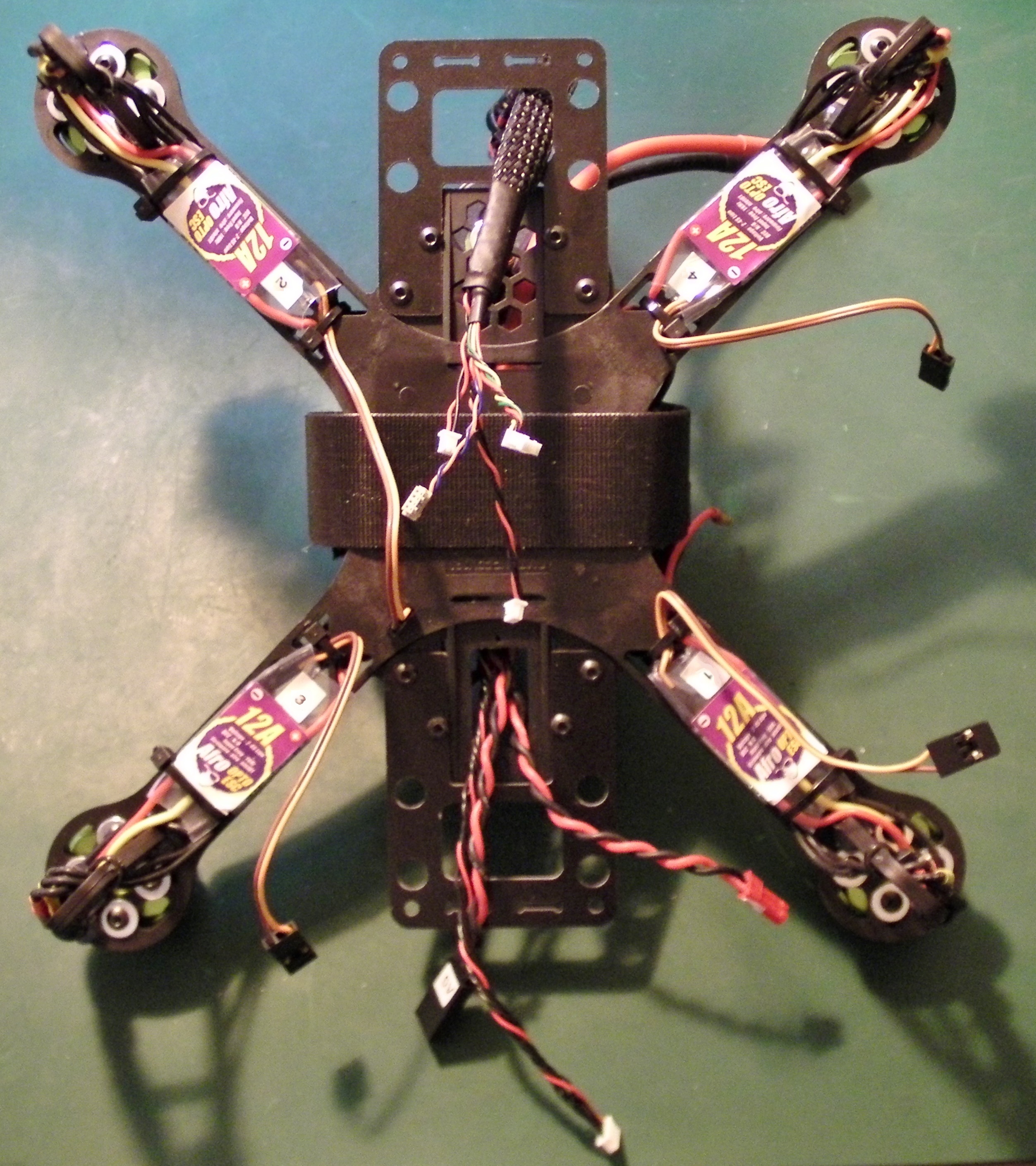
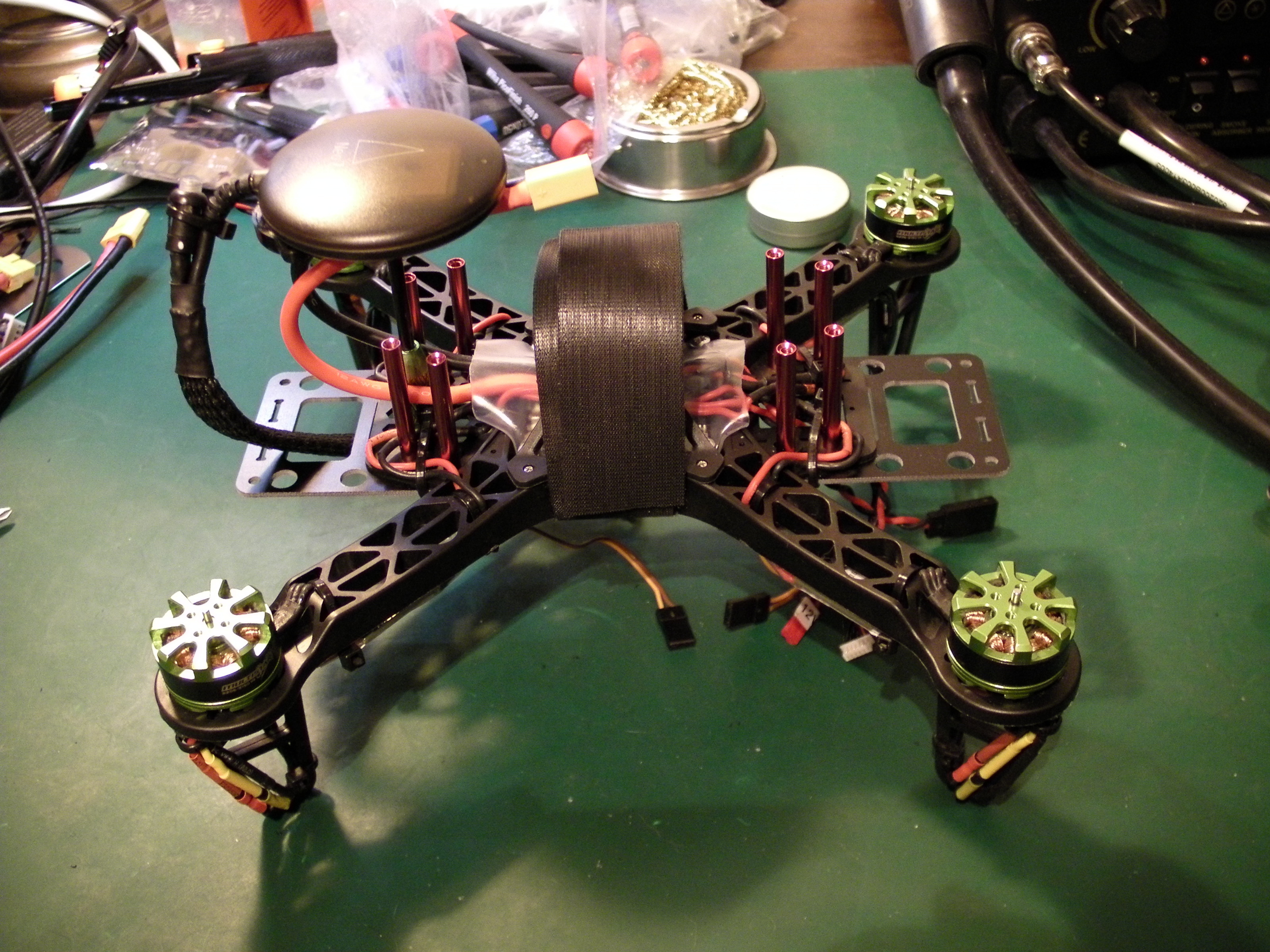
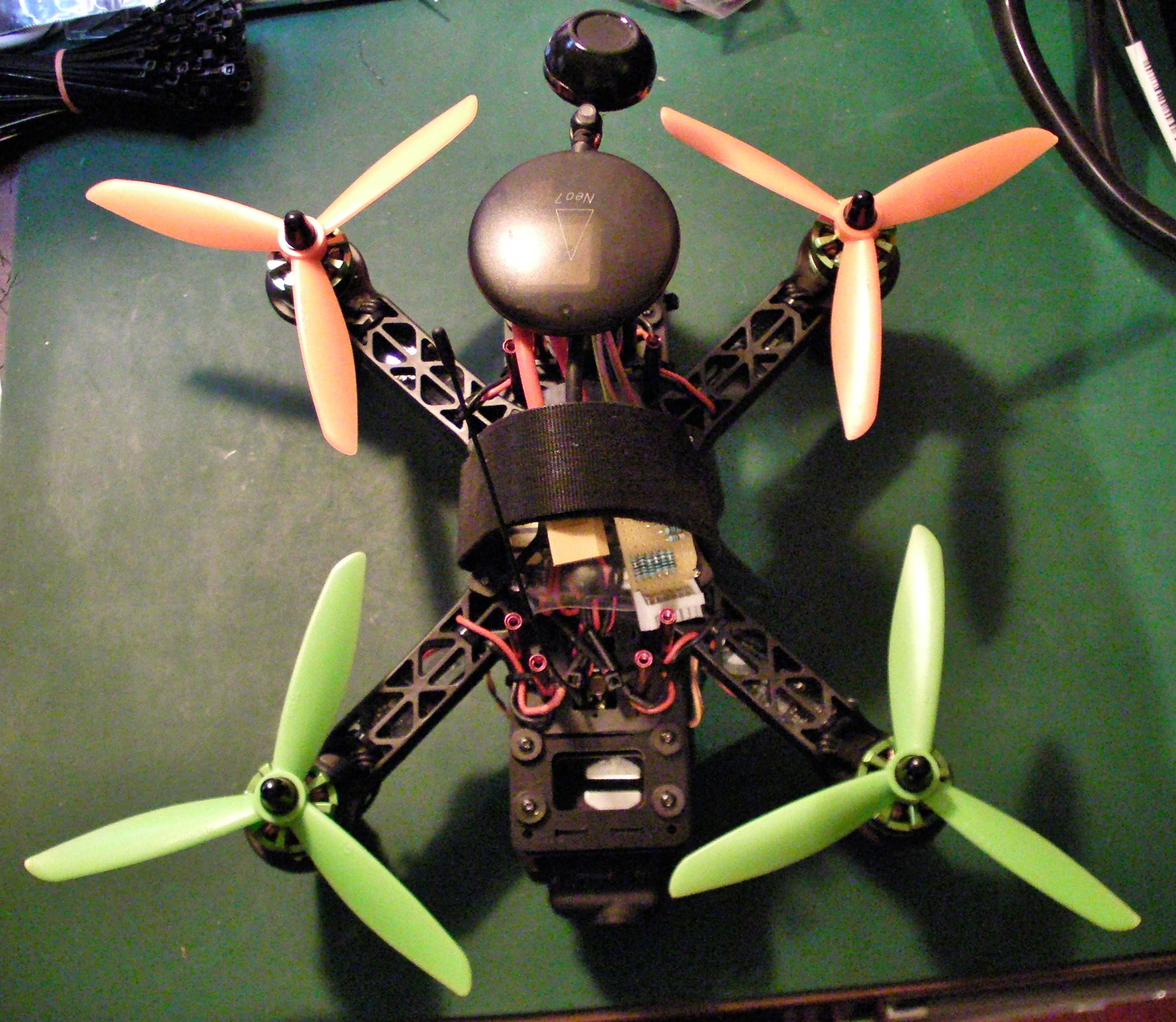
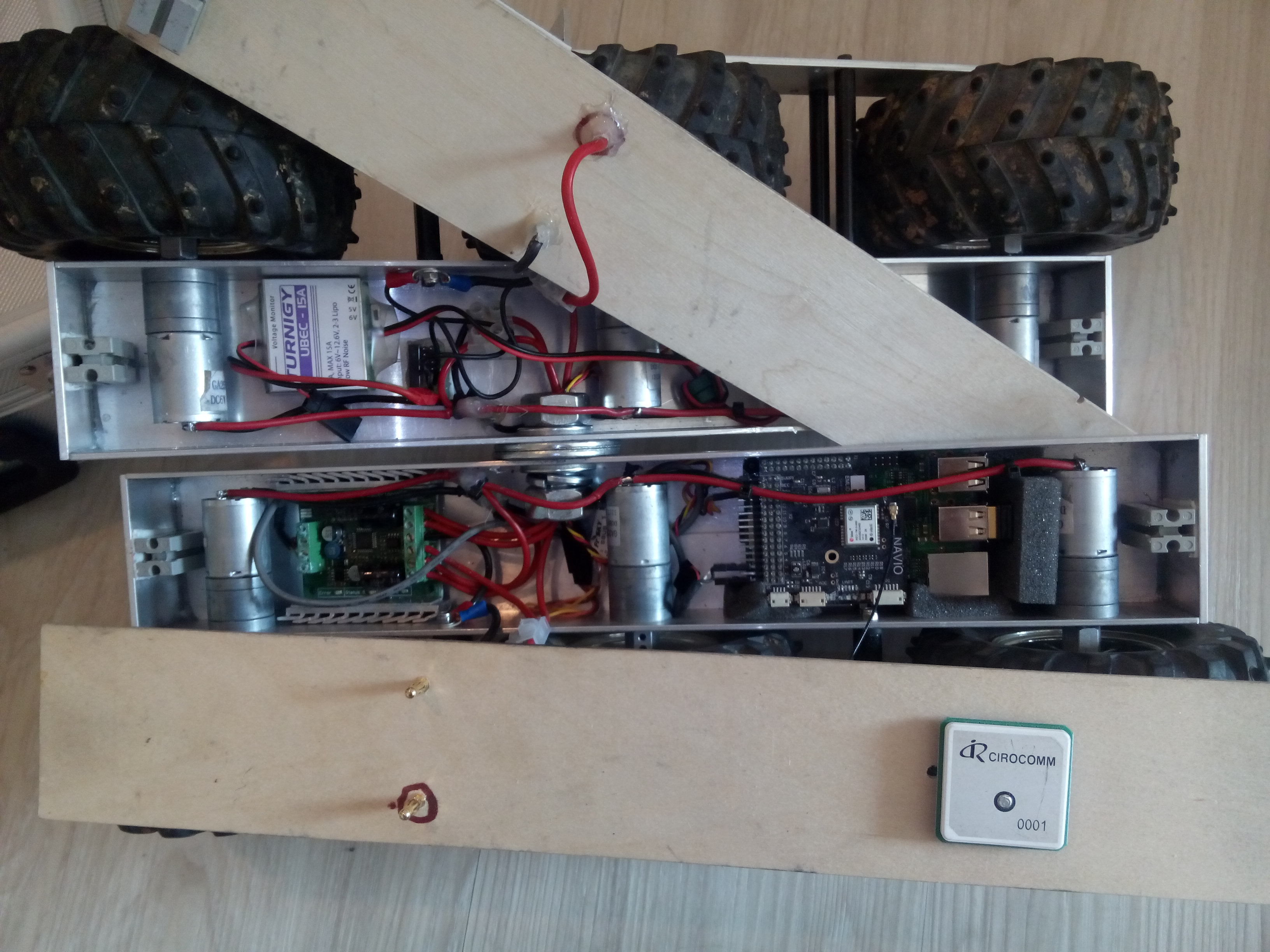
Here are some of my own pictures of the wiring:

p.s. As you may notice (from the different GPS and cable) that is from my Pixhawk build. The Navio version looks almost identical. But I haven’t documented that yet.

So the only thing not particularly clear to me is exactly how the ESC’s connect to the Navio+ Does there have to be a PDB between the two or can I just go straight ahead and directly plug in the ESC’ s in to the Navio+? Or better yet, which PDBs would you recommend I use? I’m not particularly worried about space because this is a ground based robot, not a drone. (Probably should have said that earlier)

Brushed or brushless ESCs have three connection “sides”, one connects to the battery, the second to the motor and the third to the RC receiver, Navio+ or whatever you use to control your vehicle. The connection to the Navio+ is a three pin servo plug with signal, ground and plus. If you have a ESC with a built in BEC the plus cable supplies 5V to the Navio+ servo rail.
A PDB is usually only necessary, if you need to supply battery power to multiple ESCs/loads. You could use one in a rover to distribute battery power to the ESC, BEC and perhaps Video TX, if you plan to use dedicated FPV equipment.
For a rover you can use a RC car and add the RPi/Navio+ to it, or you use a dedicated robot chassis. The robot chassis usually use brushed gear motors and are slower than a RC car. You could also build a chassis yourself, but building a wheel drive train is much more complicated than building a quadcopter frame.
This is what I came up with, after I had enough of the low quality of my Dagu WildThumper chassis:

It uses a Sabertooth 2x12A brushed motor controller to control the 3 motors on each side. It is powered by two 4000mAh 2s lipos in parallel. 5V power comes from a Hobbyking Turnigy BEC.
I do not use a powermodule in the rover, because I never managed to run the lipos dry. They last over 60min and the sabertooth has a built in lipo protection.

1 Like

I’ll probably be building something like this (Just not was the articulation and the motors might be direct drive.) Yeah, as for the frame, I’ll do it myself. I have a very specific task in mind for this (Might even require more than four motors, I hope not though) Ok, since I’ll be using 1 or 2 LIDAR units and four motors, I would be guessing that would require a PDB.

It depends on what you want to do. If you plan to build something with omniwheels, like mecanum wheels for example, you would have to control each motor seperatly. So you need four (or two dual) motor controllers, all of them need to be connected to the battery and you would need a PDB. The same applies, if you want to build something with multiple brushless motors, since each one needs its own ESC.
On my rover, all motors on one side are connected to one output of the sabertooth in parallel. One dual motor controller , one (ok, two acting as one) battery, so no PDB.
I do not know what you mean with direct drive. For most applications, you would want some kind of gearing between motor and wheels. The torque goes up and the RPM goes down. You can use smaller diameter motors and therefor build a more compact frame.

Alright, so I will need a PDB, which one do you recommend?
Alright, I’ll be now figuring out how to build a gearbox, mostly because a gearbox for my motors probably doesn’t exist.