Good evening everybody,
I just have a quick question about my current hardware set up as I’m just getting into RC planes and want to make sure that I have everything connected correctly before I connect the battery.
As I am a little anxious about connecting pole I want to make sure that I don’t blow my raspberry pie what any other electronics especially the navio+
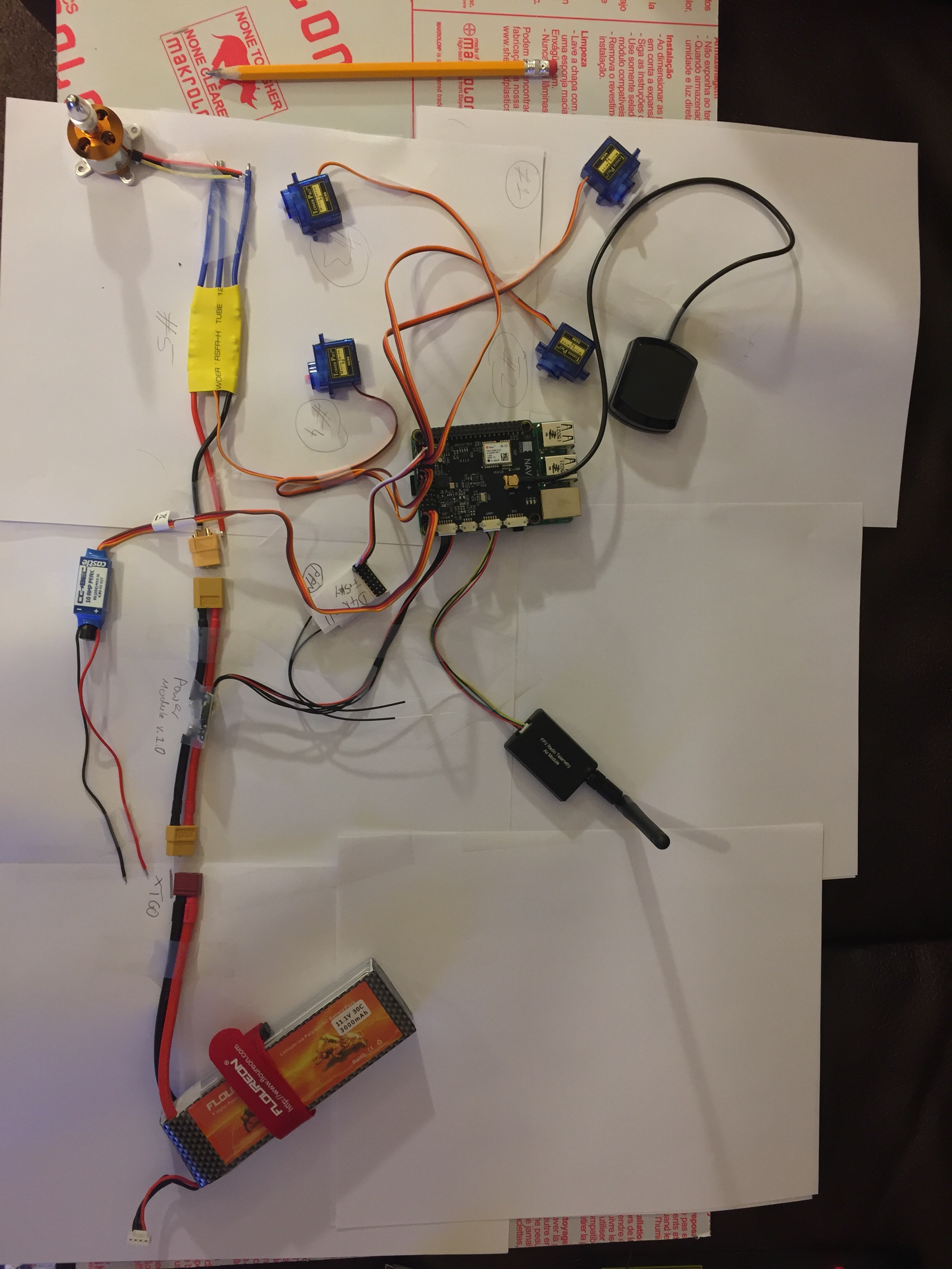
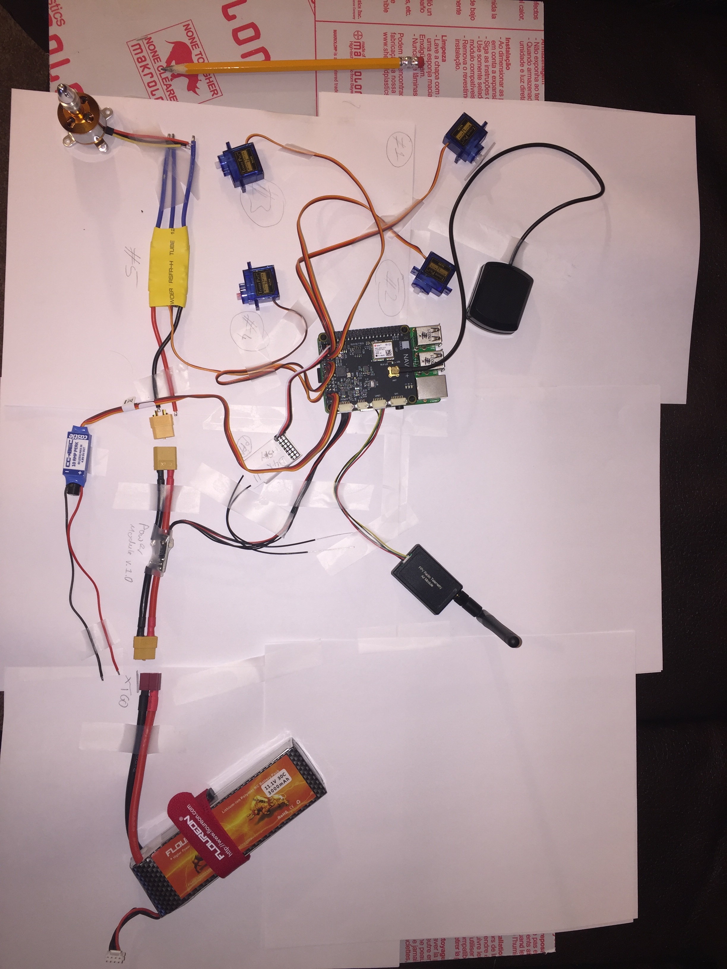
If somebody could be so kind and take a quick look at the attached picture and let me know if I have any mistakes in there
I have the following components installed:
Raspberry pi 2B
Navio+
Power Module v1.0 connected to Power Port
GNSS antenna connected to ANT Port
Telemetry Module connected to UART Port
Receiver (FRsky D4R-II) connected to PPM Port
Out-runner motor (Cheap knock off) connected to ESC
ESC (Cheap knock off) connected to Port #5 & Power Module
4x 90g Servos connected to Ports #1 - #4
BEC 10A, 6s @default: 5.1V (castle creations) connected to Port #13
Logitech C920 HD Webcam (500mA @5V) connected to USB of pi
Some sort of USB 4G LTE Modem *not yet specified - suggestions welcome
The questions that I have are the following:
In order to connect the BEC do I have to use a Y-Splitter and come right off the battery as shown in the picture and then just connected to any port? Do I need to remove the power wire of the ESC that is connected to port #5? Or can I leave it connected since I only have that 1 ESC?
The BEC can supply 10A peak, is that for this application over- or undersized? I’m putting 11.1V in there, so it’ll be slightly less than the 7A @12V IN. I will be using it to power the above mentioned hardware. Description: “@12V input = Output Current 7A continuous, 10A peak”
I have a PDB (Crazepony Matek PDB Version 3.1) on order that outputs 3A @ 5V, it has built in BEC. Does that mean I couldn’t replace the BEC that I currently have in the system and use the PDB to also power my FPV camera and video transmitter, while supplying power to the Servo rail?
In regards to the receiver:The receivers manual reads: “RSSI (PWM) and CPPM output - If CH3 and CH4 are connected by a jumper, CH1 will output CPPM for CH1~CH8, and CH2 will output RSSI (PWM); if I understand that correctly I need to put a jumper on channel 3 and 4 and then channel 1 connects to the PPM port on the navio+ is that correct?
As I am looking to use a 4G LTE USB Modem or similar at a later point, can someone suggest a good carrier with affordable data plan for the U.S.? If anything it should be prepaid, and no monthly fee or contract.
What have people with similar projects based in US used before?
- Do I need a telemetry module as seen in my picture? Or can I use a combination of any other device that features telemetry?
And yes, I will exchange the connector on the Battery to a XT60 plug and connect the Motor leads accordingly.  please ignore the small obvious errors! Thanks
Any comments and suggestions are highly appreciated.
Thanks Guys!