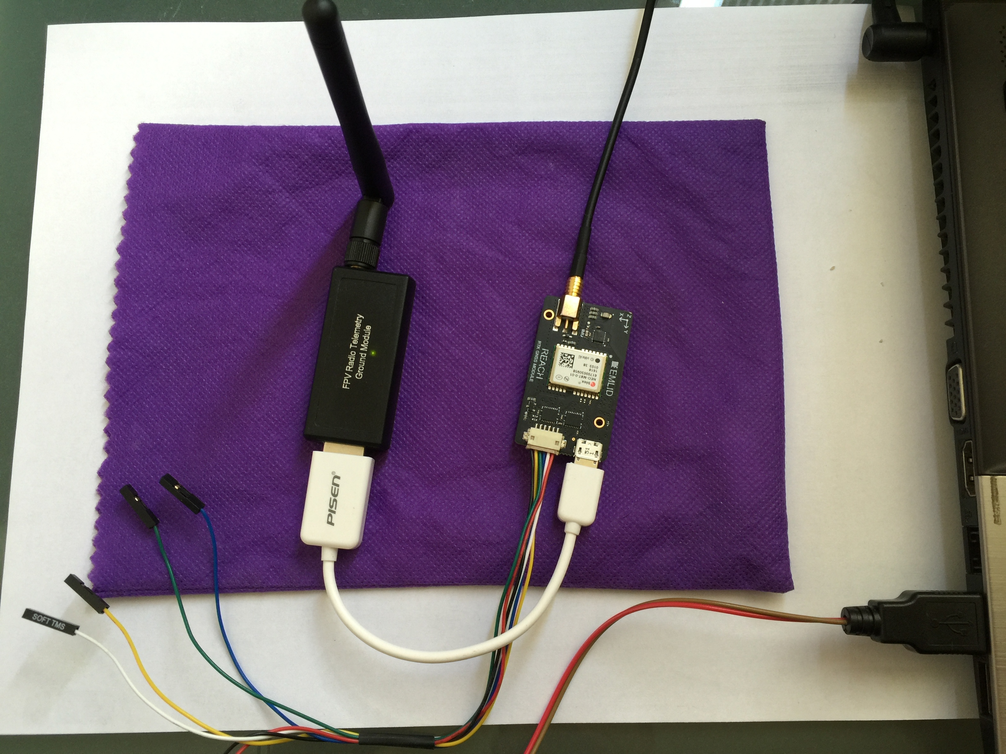
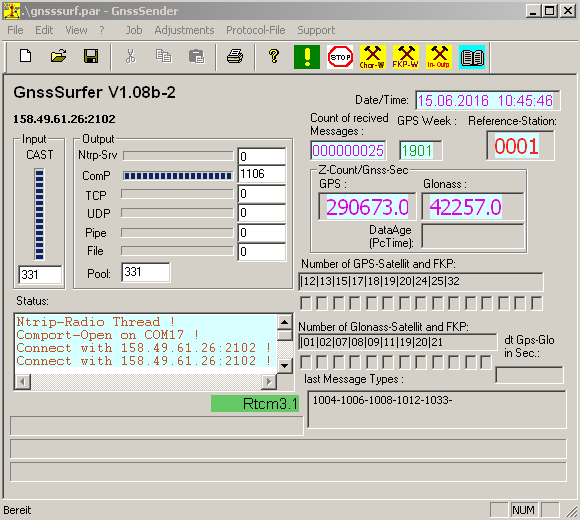
I connect the USB part on my computer and I run GnssSurfer software. I configure the connection to the nearest mountpoint by an NTRIP client in GnssSurfer and I configure to send an output to the COM port where the USB radio is connected with a baud rate of 57600.
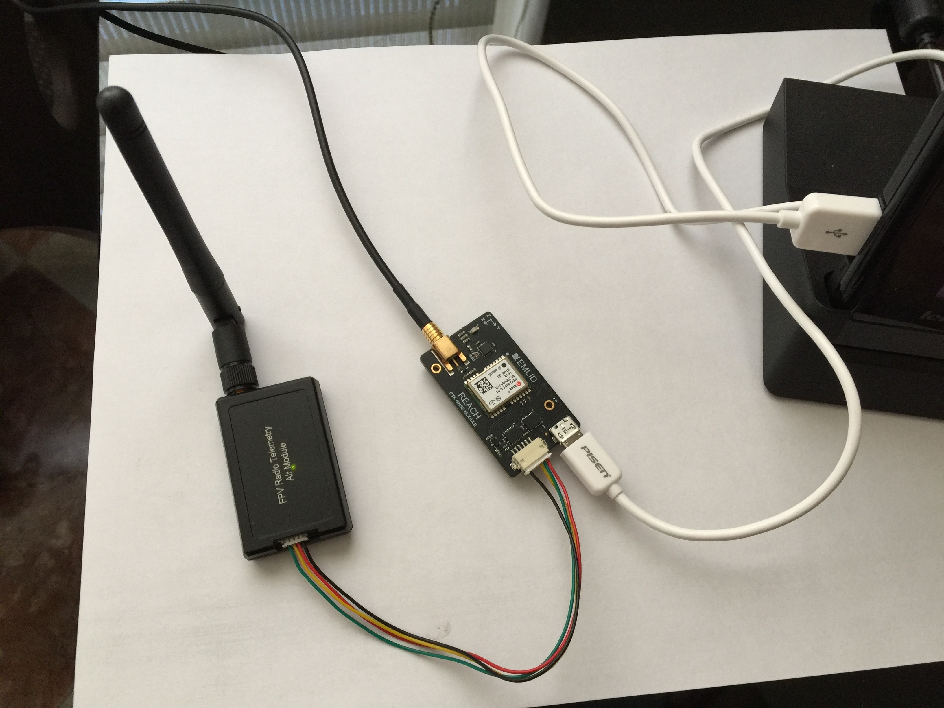
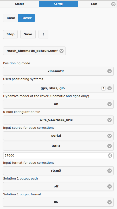
Then I connect the other 3DR radio part with DF13 connector to Reach and I power it by USB. I turn on the reach…I access to the ReachView App and I configure (as rover) the input source for base corrections as “serial/UART” and 57600 bauds.
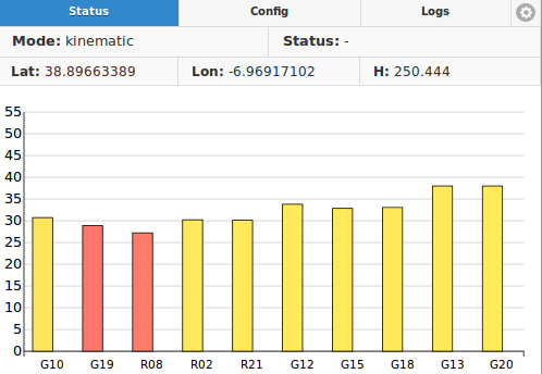
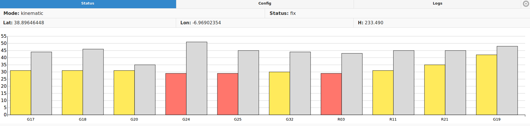
I start the Reach device and the gray sat bars does not appear… I dont get any status too.
What am I doing wrong? Is there another way to send corrections from an NTRIP using a PC and one Reach configured as Rover??
Thanks!
EDIT:
Radio → 433MHz
Reach Image version → v1.2
ReachView version → v0.4.2
and the other uses the wiring harness to the Reach. The one connected to the micro USB from the radio to the Reach should be configured differently if used on the Rover. Instead of:
Serial and UART it should be Serial and USB. I tried it the other way and saw no gray bars.
Other posts say that this makes no difference but it did in my case.
Also, on the Base the RX and TX wires must be crossed so that they are not RX to RX and TX to TX. They should be RX to TX so you must cut these, cross them and solder and shrink wrap or tape. The Base unit sends out a continuous signal to the Rover and the Rover has not need to communicate back to the Base. This is covered in some of the earlier posts on similar radio posts.
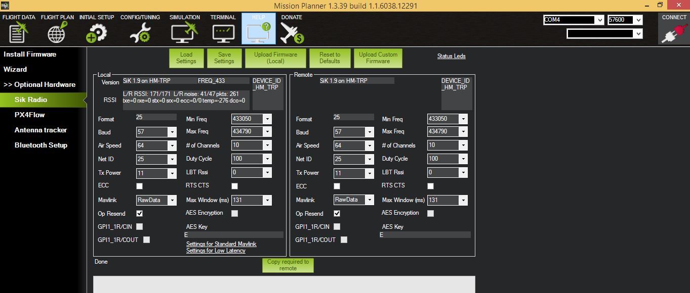
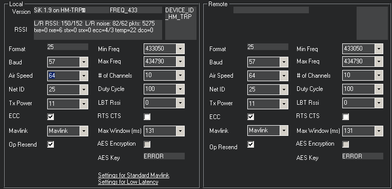
It is very important to have the same baud rate for each radio so I agree with Igor. I downloaded Mission Planner and used it to mainly check the baud rate of the two radios.
My first set of 3DR radios had one bad radio and even after updating the firmware using Mission Planner this did not solve my problem.
My second set worked and actually has 500wm output instead of the 100mw most of the 3DR radios come equipped with. I found them on Amazon.
Today I checked the radio configuration with Mission Planner and both had the same config.
After that, I unplugged all pins in DF13 connector and I connected them making sure (again) TX <—>RX
I don’t know what specially I did but now it’s working!!
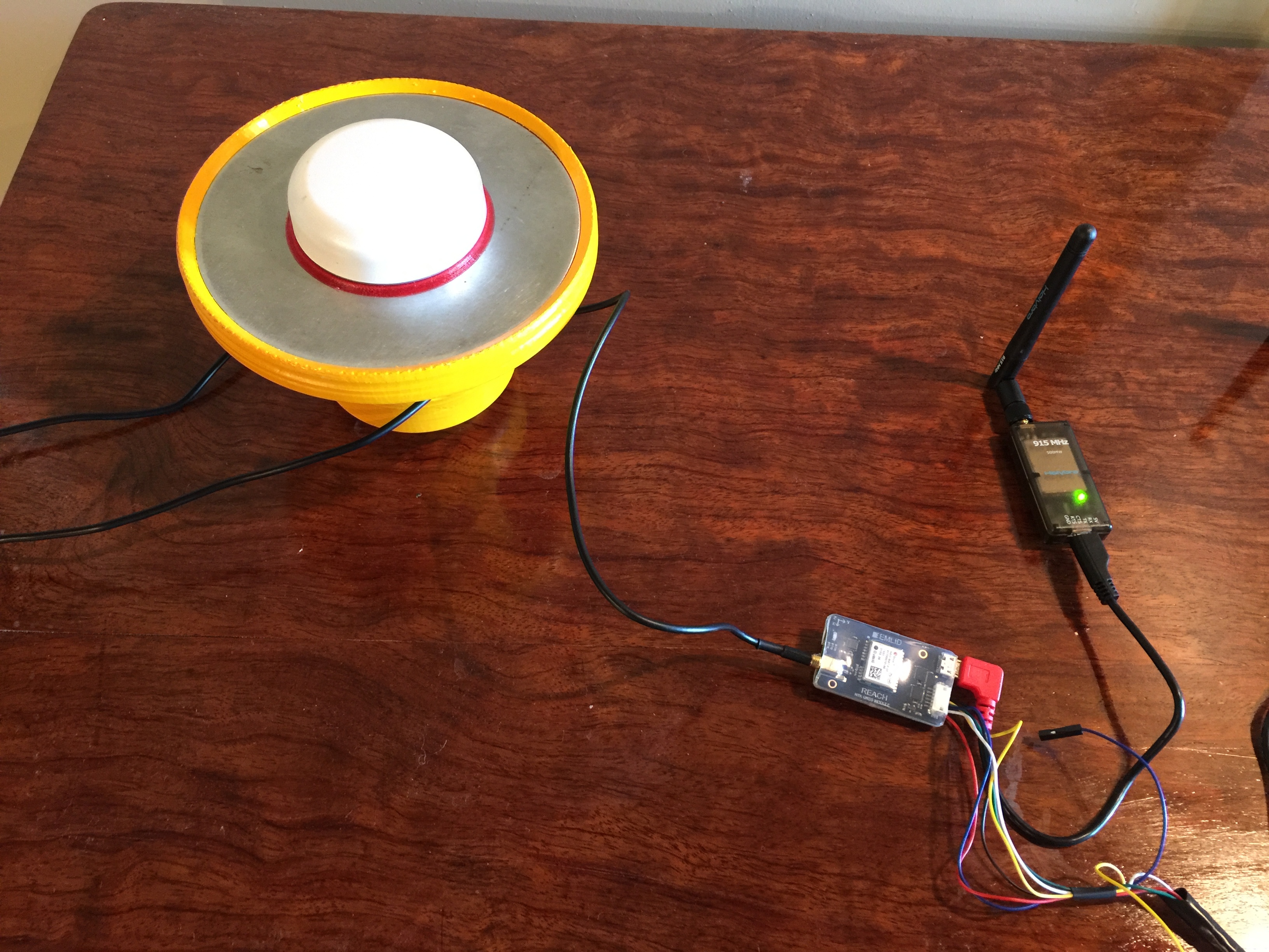
Did you build your antenna case with a 3D print? do you have any 3D models?
How many kilometres range could you get with this 433Mhz 3DR radio?
Would be possible to start the reach without reachview app??
My mount was 3D printed and is very tough, made of nylon. It was designed and printed by a 3D printer who makes auto and tractor parts. This type printing, as I understand it, is done in a chamber. I can give you a link to the engineer who made these mounts. His design is a work in progress.
My radios are 915 MHz and I do not know the range but they seem to penetrate some forest cover and the longest range used thus far is about 400-500 meters. Open line of site they will transmit over a much greater distance I suspect.
Also, if you have trouble getting a Fixed solution with the Reach kit antennas you received, I upgraded to antennas that get a Fixed solution within about 2 minutes on startup and with fairly open line of site for the antennas. They are TW3710 and the same antennas that Larry Rauen recommends except they also receive Gallileo signals. Our devices cannot process that constellation yet but it is coming according Igor.
The reach will start when it receives power. Not using Reachview, though would make it very frustrating to use as you would need to communicate with the device and ReachView is build into the device. For me it would really be a time waster and increase the learning curve. It is very nice in the field to see the signal and know the quality of the solution as I collect data using my iPhone or iPad. That way, I know to stay on a point if the GPS signal to the antennas if scattered by tree cover.
After a power cycle, Reach will start in the same configuration you left it, so no need to reconfigure every time. Keep in mind that the logs might fill the free space very fast.
Hi Jorge,
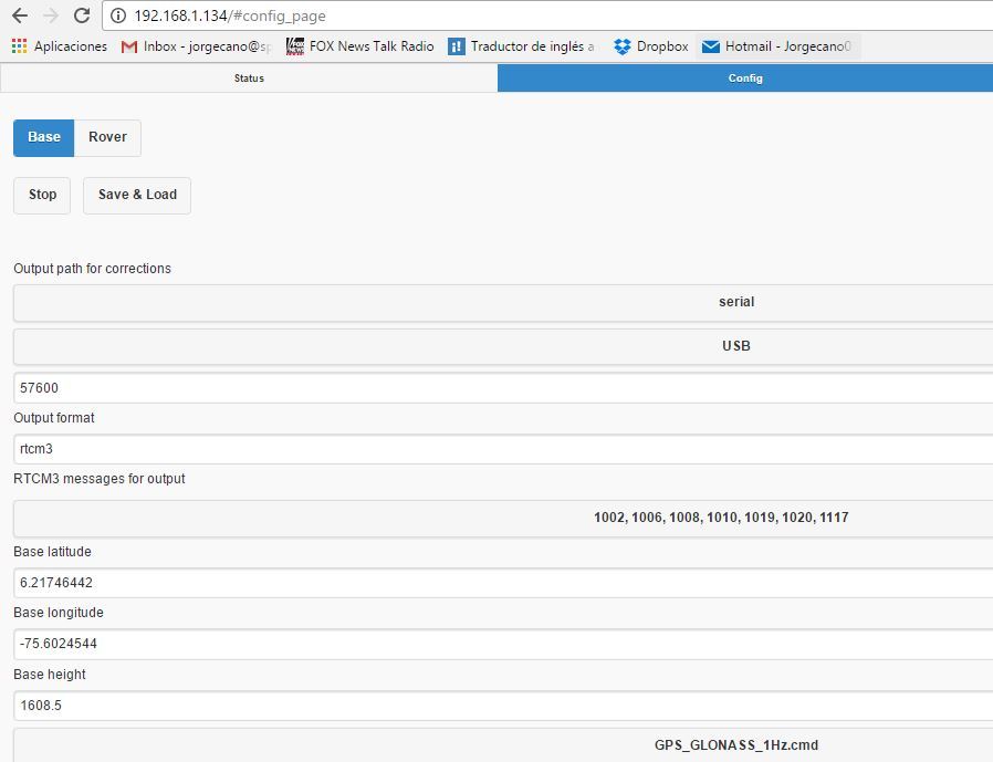
The Reach config. we have used was which I put on the screenshot above. We only have 1x Reach device, then we configured it as Rover. In this case we are using a software PC as Base.
In this software we config. as input the NTRIP credentials (user, pass, IP, port, mountpoint…) to get the stream of data and as output the COM port where my USB 3DR Radio is plugged.
In The ReachView App you have to config the input source as UART, then you have to connect the other 3DR Radio antenna to propper Reach pins (UART).
I haven’t this configuration now I hope this could help you.
PD: If you speak spanish you could send me a private message here and I will explain you what you dont understand
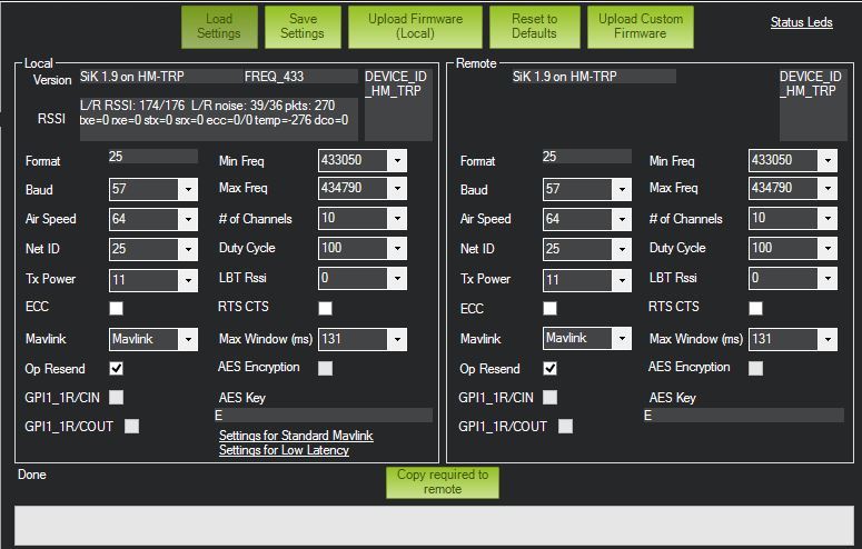
For completing my explanation of the problem, I am sending you a screenshot about analysis with Mission Planner when connecting the ground antenna to my PC through USB port and the other antenna (remote) connected to my tablet.
It seem everything is OK, but when unplug the antenna and connect the Reach module, nothing hapens.
Thanks for your posting
So, If I want to link Rover and Base with Radio module, Rover should receive correction from the USB, and Solution output path should be the DF13 port?
Do I understand it properly?
And can u please check the configuration also?
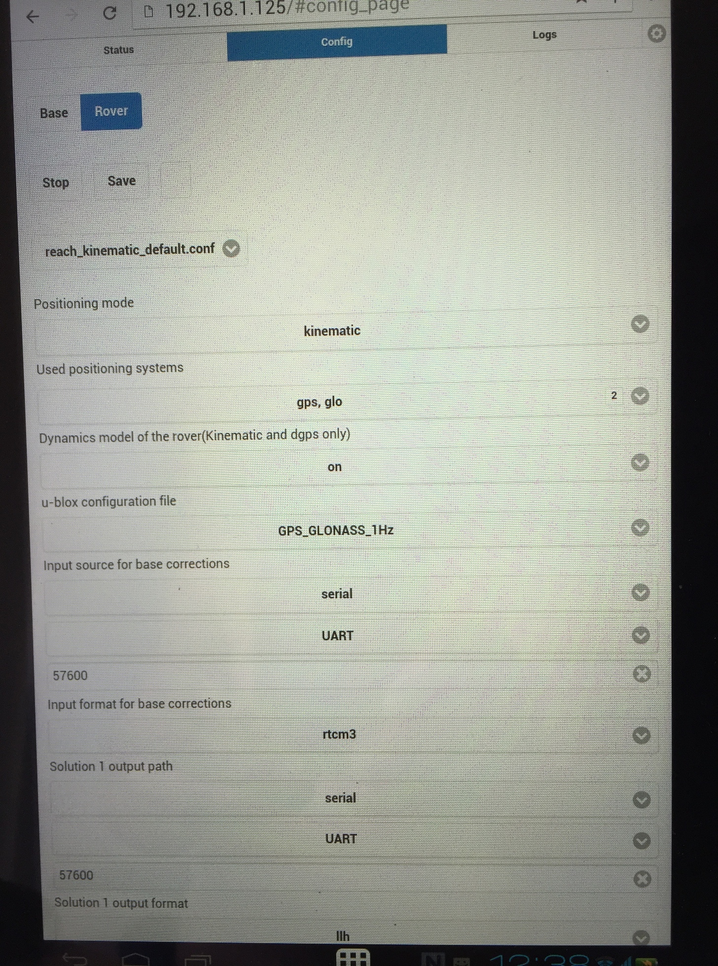
This is my configuration screen. And I can’t choose e UART or USB. When I set the “serial” there is only UART. What should I do. Please answer my question who already make it.
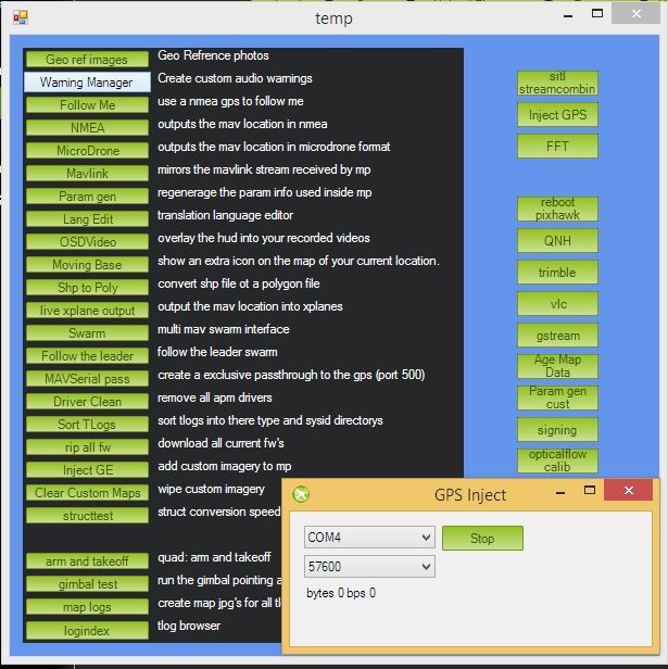
I already have done that you say, I put mavlink in rawdata, I going to Ctrl F and select inject GPS, and, on the box I type port and bauds, and… I dont know if they are communicating.
That’s correct but you pick the IP of the base station, Not the com port. The port number should be 9000 unless you have changed it in reach base station.
So just as a final check.
If you are using your local area network, the IP address is the one given by your router. If your laptop is connected to the base station access point as it should be then just verify the base stations IP and put that in the GPS inject. You should now see date flowing and the grey bars will appear in the rover
I think that what @Jorge_Canois trying to achieve is just a direct radio connection without passing data through the autopilot, so there is no need to use Mavlink Inject. This feature is needed solely for injecting correction stream into drone telemetry.
Your base station radio is connected over USB, but settings are “UART”. This will not work. If you can’t see USB as an option in app it might be that chip in your radio is not supported by Reach at the moment. Intel provided an old driver in the image and we will address this in the next image update to ensure that all devices are recognized.
Can you connect your base radio over UART as well?
@egor.fedorov posted a temporary fix for the USB not being recognized:


 I hope this could help you.