Hi! I was not able to find information about 5V/1A output on this PDB, only about 2.5A UBEC which probably has output on the power port. Servo rail should definitely be powered from a separate power source. OptoESCs probably won’t consume a lot of power from this side, but it’s better to check the specs anyway.
Yes, 2.5A should be more than enough for RPi and Navio.
It is okay to power then from the BEC on the PDB, no need for another one.
Servo rail has to be powered from a separate source.
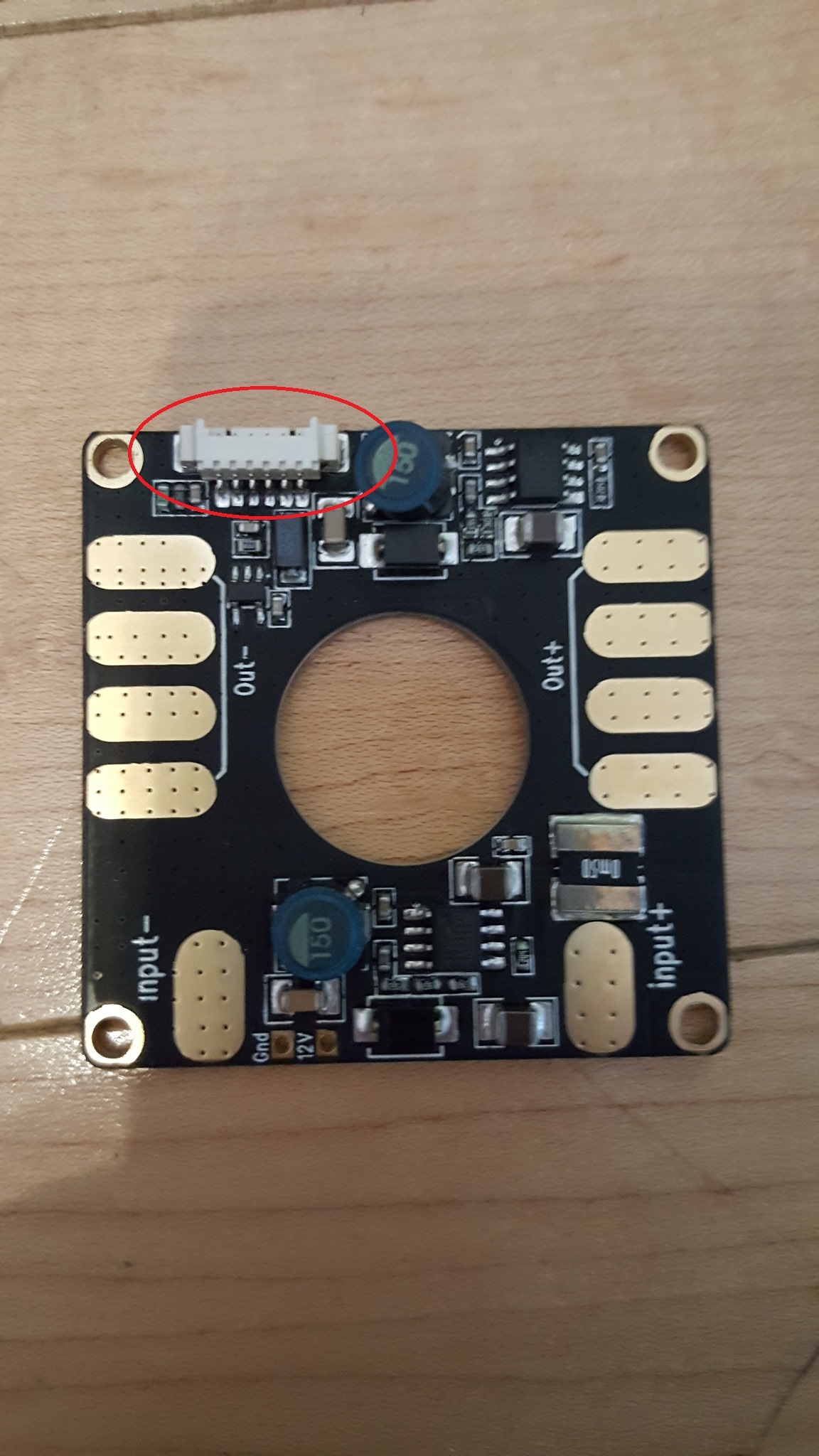
I can solder the servo rail power wires to the contacts highlighted in orange. Any idea what the I and V contacts are for? My soldering skills are sloppy at best and I’m a little afraid to unsolder the 6 pin connector that is on the other side.
Or even better to solder the BEC to one of the Out+/Out- contacts and keep 5V and 12V outputs for other devices. I’m a beginner and it’s hard for me to plan ahead in this case (like to use 12V output for a camera seems logical).
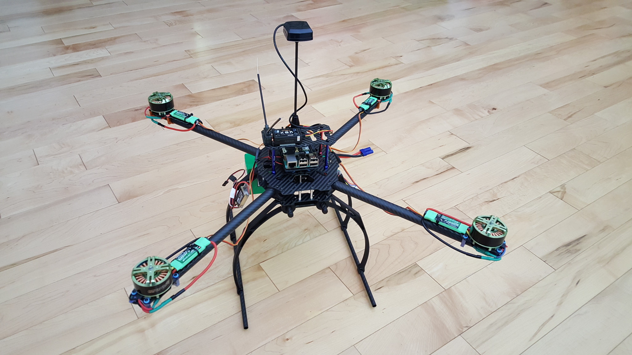
This is a PDB with integrated power module.
I = current sensing output
V = voltage sensing output
Do not solder anything to the pads. They are just a duplicate to the 6 pin connector on the top.
Connect the 6 pin connector to the Navios power port and it will power the Rpi/navio combo as well as providing voltage and current sensing.
You will need a seperate BEC to power the servorail.
That’s what I did. I soldered two BECs that I mentioned above to two pairs of Out+/Out- connectors. One to power the servo rail and another for future use. Seems to be working fine. I connected everything and it booted. Getting 'GPS: No fix". Reading threads on that. Looks like before I can get past that I won’t be able to arm the ESCs and test the motors.
If you are indoors and in a city, you will have a hard time getting a GPS fix. Just connect Missionplanner or whatever GCS you use to APM and search the full parameter list for “arming_check”. Set it to 0 (and click write) while you are testing and do not forget to reenable it before you go out to fly!
As soon as you raise the throttle all the stabilization calculations start. It is not advisable to let the copter sit with throttle raised and not taking off. Especially the I-Term of the PID algorithm tends to wind up on sensor drift alone. While testing with props off, nothing bad will happen, but if you do this with props, the copter will eventually tipp over as soon as you try to take off. You will never see all motors run at the same speed for a long time, as long as they are controlled by an armed/flight-ready flighcontroller.
PS. I got a modified vibration dumping mount to fit this frame. Same as the one in the docs but modified lower part. I had to dremel it a bit but the guy who printed it for me promised to adjust the files and I will share when he’s done.
That shouldn’t prevent me from flying LOS, correct? I got all hardware in the Initial Setup in the MP calibrated. Still finishing reading on Flight Modes and Failsafe. And the props (APC Slowfly) are still not balanced.
But I want to get this thing into the air… just up and down. To test if it will even fly.Just increase the throttle… Any recommendations/precautions?
Another question. Is it OK to use rubber cement to attach the protection piece for the barometer? Should the black foam from the metal boxes in which the motors (Turnigy Multistar) came do? Or foam pad from an old motherboard packaging?
So I tried to take it in the air yesterday. It was lifting off but it seems like the battery throws the weight off balance. It did rise about an inch but it was sliding backwards and fell on its back side. Damaged the props a little bit. Just chipped it in a couple of spots. Can I fly on slightly damaged propellers while waiting for the new ones?
I double checked the motor order but that seems correct.
I thought the autopilot would compensate for the weight distribution.
The foam has to be an open cell type. It’s hard to say which one comes with the packaging. You should be able to breathe though the open one if it’s not too thick.
It’s not recommended to fly on damaged props. They cause vibrations and may result in damage to the hardware.
Regarding tilting on the take off please read the troubleshooting section in the Ardupilot docs.


 Was going to read up on that.