I am trying to incorporate a basic echo/trig based Ultrasonic sensor (HC-SR04) with my navio 2. I want to take this input and be able to view it in Mission Planner.
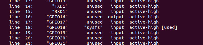
The way I understand the GPIO system working for Navio2 is either via the GPIO 17 & 18 pins on the UART. Or by setting servo rail pins to be GPIO.
I am currently trying to use GPIO 17 and 18 with no success. I have been setting “RNGFND1_PIN” = 18 and “RNGFND1_STOP_PIN”=17 in Mission Planner.
My logic voltage is 3.3 and I know the sensor works. Arducopter version 4.6.0beta1.
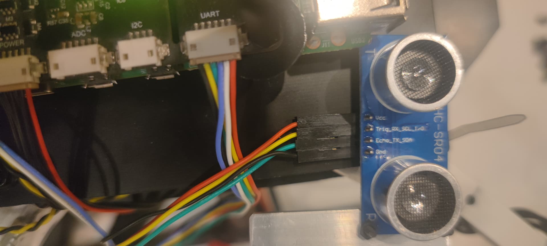
Hi @merryna.anggriani , no, it’s connected to UART port, used standard navio2 wire, where red +5V, black GND, yellow GPIO17, green GPIO18, and blue and white TX RX not used in this setup. From the navio2 pinout we know that GPIO17 and 18 are free to use.
I ended up going with a I2C ultrasonic (GY-US42) instead of solving my issue. I was on a time constraint for school so I didn’t have too much time to miss with it; but I wish you the best on getting this working!
I believe where I got stuck was assigning the pins, arducopter will only let you assign GPIO# 1-50 or something like that. But the navio2 assigns GPIO from 301-350. It was this 3XX gpio address difference that I think was limiting me.
@ddogh101 , Thank for the wishes! Yes , there is an option to use I2C , but it’s already occupied. Moreover it’s too wasteful not to use working GPIOs on Navio2, when other standard RasPi pins are occupied. And yes, it might relate to pins mapping, a lot of open boards have file (hardware definition) where defined some mappings. Since navio2 is closed board, there is no info about that, Emlid support should explain how to use those two GPIOs with arducopter. @merryna.anggriani , hello! Any news about our problem?
Hi @merryna.anggriani , yes i have, i also noticed that mapping in Ardupilot code GPIO_Navio2.h. 14-> IO17 15->IO18. And this changed the picture a little bit. Arducopter is using now Echo Pin(RNDFND1_PIN) (15->IO18)
But still it doesn’t use trigger pin(RNGFND1_STOP_PIN) 14->IO17. I noticed that for RNGFND1_PIN 14 and 15 port numbers have correspondences ( 14->Pixhawk ADC3, 15->Pixhawk ADC6/Pixhawk 2 ADC), so for example if we wanted to use pin14 as RNGFND1_PIN, it would be also used by Ardupilot. But for RNGFND1_STOP_PIN no default correspondences for 14 or 15. I don’t know for sure but it seems like predefined choiсe.
I spoke with our developer about this, and since it’s not a standard setup, troubleshooting could be challenging, especially since we don’t have the same range finder to test with. However, I’d recommend checking the ArduPilot forum, where experienced users might have encountered a similar setup and could offer valuable insights. I also came across some relevant threads that might help. Here’s the link.