This is really a question for MicroSurvey FieldGenius9 forum, but it takes EONS to get any sort of response at their forum as not active like Emlid, so trying here hoping to get some help from other FieldGenius users or even similar situation from SurvCE/PC, Topcon Magnet, etc users?
Using a Reach RS for ROVER and a Reach RS for BASE.
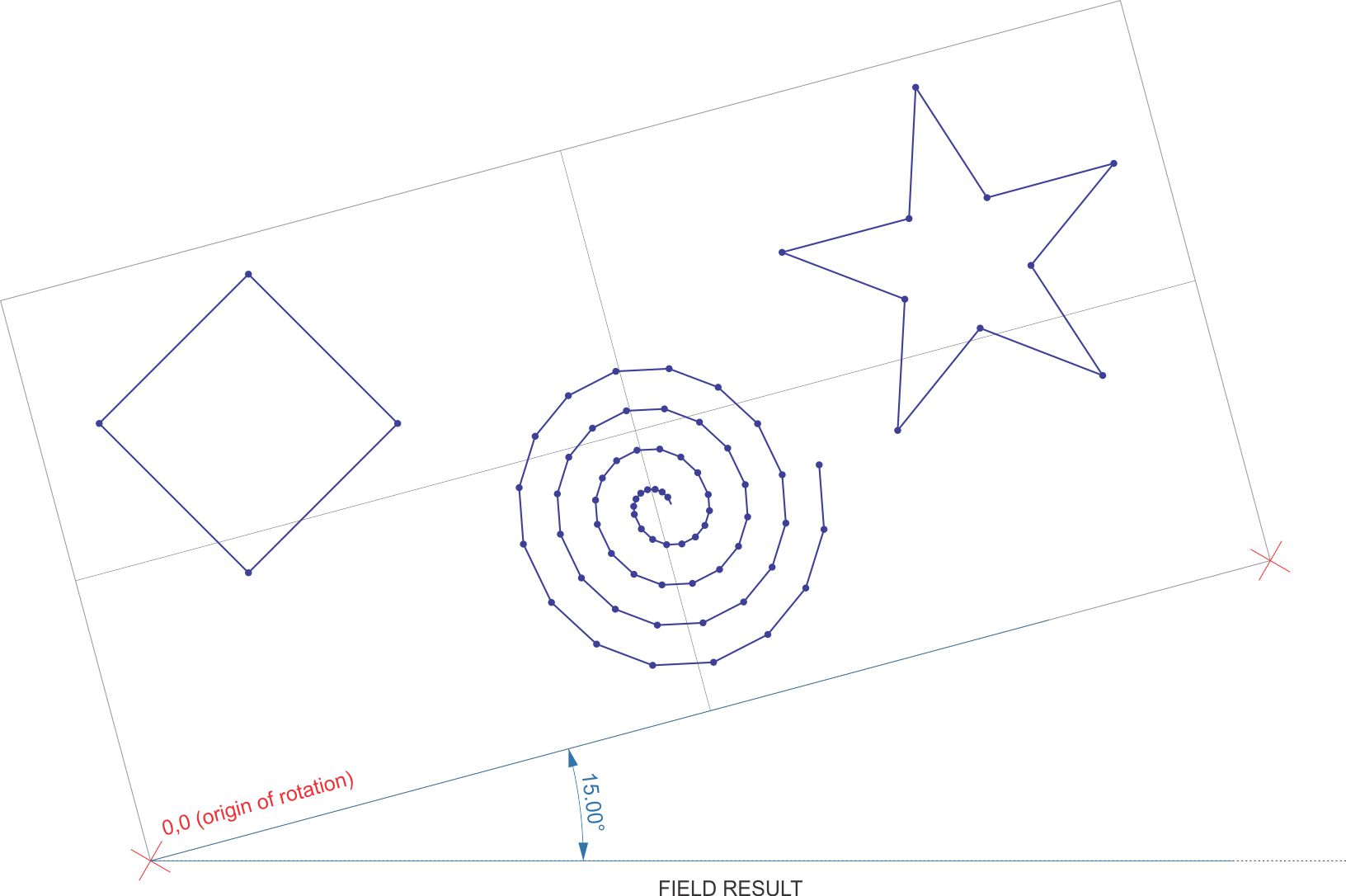
Besides using this feature (GNSS Local Transformation) to TRANSFORM my points AND coinciding DXF imported linework (which is turned on in the layers manager) to my GNSS ROVER position when in the field, is it possible to also ROTATE these same points AND coinciding DXF linework? I can use Rotate / Transform / Scale to do this with the points only (after using GNSS Local Transformation to move my points to my GNSS location), but obviously the prior coinciding DXF linework will not rotate with the points.
I am “hoping” that using GNSS Local Transformation will accomplish this using either at least 1 control point and provided angle of rotation (I.e. 15 deg)or 2 control points, rotation determined by the angle between the 2 control points.
All in all,just hoping to design the points and linework using typical cartesian coordinates system in my graphics software with origin of 0,0. Then get to the field,set up my rover on my 0,0 origin and then do a GNSS Local Transformation of all the points to get my points to the origin in the field, and then rotate all these points and DXF linework so I can stake them at. The DXF linework is used so we can make things out better as there are about 500 points.
What kind of work is it for? This will determine what kind of localization you need to do. FieldGenius does both the methods you described, but please do not provide site data based on anything less than a 3-point localization. Single and 2-point are good for alignments and slope staking.
It’s non-typical work. I.e. not really for surveying use by say a registered surveyor. So vertical isn’t a concern or need to come into play. Mainly just for use of staking out many points of objects on a generally flat terrain. Just as a guide in the end really.
I guess my main question to simplify things:
Is the purpose of using the feature, GNSS Local Transformation, not only meant to get your drawing (points and DXF linework) localized to a control point in the field, but to also be able to ROTATE it if I need it to be? I don’t need to SCALE it. Just transform and rotate the points using 2 control points in the field. 1 point is the origin for transformation and ALSO the same point ROTATION is based around. The other point is used to determine the rotation or to hold the rotation to.
3 parameter horizontal transformation. Rotate, translation in X, translation in Y. NO scale.
I’ve used GNSS Local Transformation just to localize using 1 point. Just not rotate or scale with it. I can use RTS seperate feature, but then my DXF line work doesn’t RTS with points. I know I can just predetermined all that and draw everything rotated before hand, but my plan is to be able to just rotate in the field in the field when I get there in my case. Obviously for other typical work, you would survey and collect control points, design according or around that, then come back and stake out the design holding to those initially obtained control points. But my work doesn’t follow that. I will have to adjust by transforming and rotating the 1 and only time I go to the field to stake a design around 1 central origin.
I’ll have to defer to an experienced FG user. I use Magnet personally, but have been doing allot of reading on FG and will probably move over since I can’t quite get Magnet to do everything I need because compatibility reasons.
It doesn’t look like either allow you to align your linework with the points. I normally get the localized control points first, bring them into CAD and then put the design in. You may be able to create linework by points and offsets. Sorry I can’t be of more help.
Totally get what you are saying and I have the same problem sometimes. I think yours might be worse because you are probably moving it allot more. Our localizations are normally less than 0.2’ and prorates the coordinates according to their deltas in comparison to the rest of the network. We call the FieldGenius “localization” an alignment.
I am starting to think that for my situation, that the GNSS Local Transformation feature isn’t completely what should be used in my case. It’s perfect for moving my points and origin into my GNSS lat long location, but not for also rotating everything also as illustrated above?
I’ll have to look at the Helmert method and also keep trying.
I wonder if there is a way to convert my DXF linework to native FieldGenius linework, so I can just RTS after gnss local transformation?
I’ll have try creating the linework first also in MicroSurvey CAD and export raw file also to see if that works, but would rather just export from my other graphics software versus MS CAD.
You should be able to import a DXF directly. I know it is an extra step, but it can be done in the field. Shoot the points and localize. Then bring the points in and design accordingly.
Yeah, my process is basically the opposite and not typical. I’d design before in the office, then stake in the field after I arrived there. Basically just holding to a central control point and rotating everything, then staking.
I received a answer from a very helpful MicroSurvey tech (not the forum, the forum is not very active).
Basically when I import the DXF, then convert the dxf LAYER, I can select to INCLUDE the linework (not just the points) and I can do a GNSS Local Transformation then a RTS to ROTATE all the points INCLUDING THE LINEWORK. I wasn’t including to convert to linework option, just the points which threw me off. So I think this may work. I still have to try.(THIS SOLVED IT!) NEXT TO TRIMBLE SOFTWARE, MICROSURVEY FIELDGENIUS IS AWESOME!
Thanks Micheal for the help, there aren’t very many people here but a handful it seems that actually use the feature-rich third party survey software yet that can relate. So thank you for helping the best you could, much appreciated!
I was looking back at some of the more helpful post and I felt the need to clarify that I personally don’t agree with scale/rotate/aligning the linework with the localization. The integrity of the linework whether it be a survey or design needs to be maintained. I cannot change structural dimensions, linear footages, slopes and etc… I think @timd1971 may have just been referencing alignment, but wanted to make sure it was understood.
Can you clarify what you mean? Rotating and aligning are a normal part of any land survey when you choose a basis of bearing. And scaling can be used to get ground distances from state planes. I wouldn’t necessarily use two points to scale geometry to match up to, however.
I actually have figured out what I needed. It’s wasn’t “survey” specific.
I was thinking that GNSS Local Transformation was something like RTS (Rotate Transform Scale) where I needed to do all of this in 1 shot.
But really I’d use both of the features as (2) separate functions. RTS before or after. And GNSS Local Transformation to localize. i.e. get my drawing design (DXF objects) and it’s origin localized to the site in the field when I get there based on a GNSS point I measure in the field. I could use RTS after or before. i.e. rotate everything 45 deg, and/or scale etc also.
I agree with you and I have been surveying for a long time. This is what I didn’t agree with. The linework cannot be scaled. As of his last post he is now clear on what a localization is.
Sorry for any confusion, it was for something non-survey specific or construction specific such as staking out property corners or pinning a house for building. ; ) Yes, I agree, that would not be good to go “forcing” all the linework willy nilly to what I want in the field using RTS with HUGE residuals! : /
Thanks for the help as usual… someone at MicroSurvey had emailed me with the PROPER solution, so all good now!