RE: RS2+ as base on a known point.
Emlid Flow v8.9 on Android 13
Corrections being sent via Emlid
Rover: RX
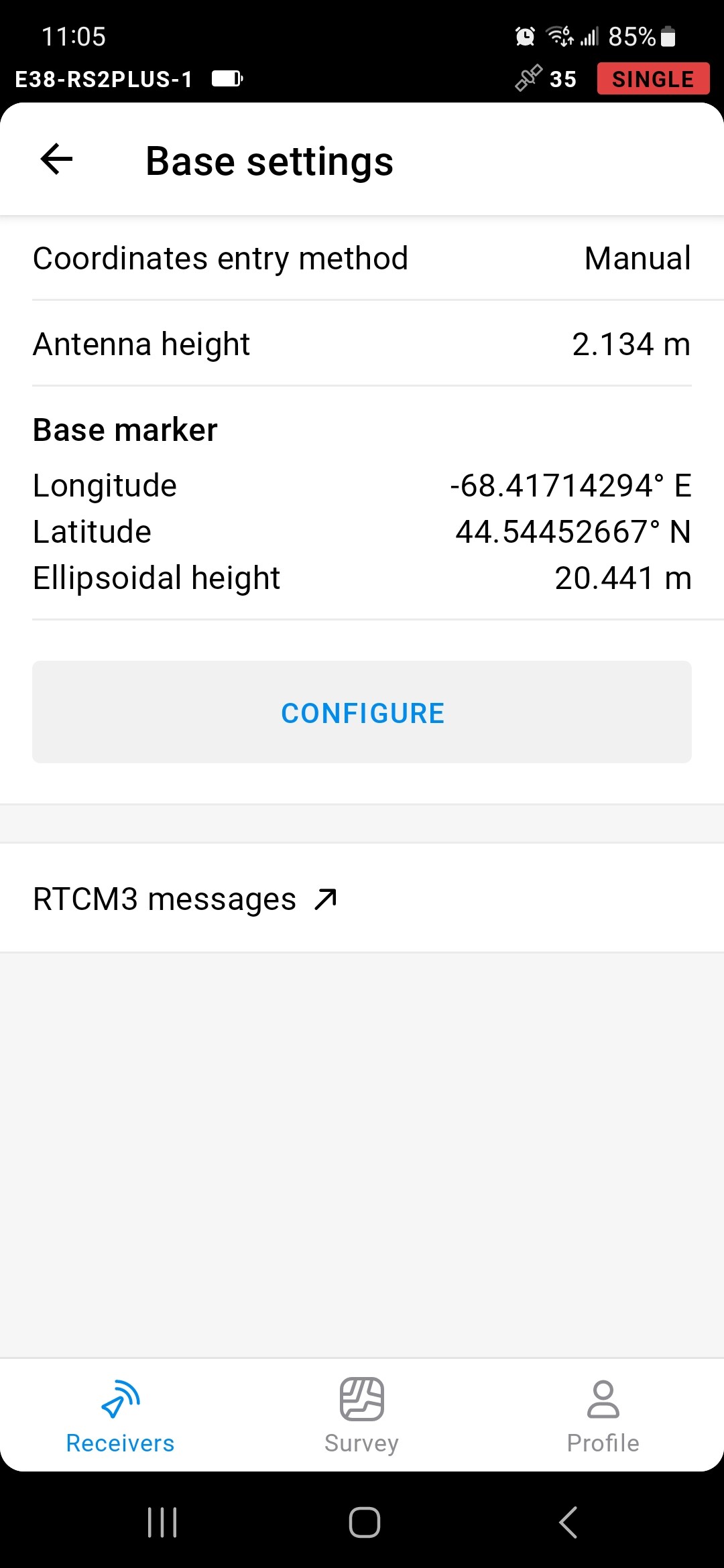
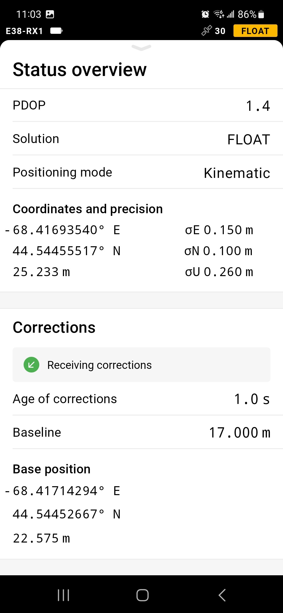
The manually entered geographic position (epsg6319) for the base is correctly recognized on the rover, though noting the 9th place value has been truncated for the lat and lon.
The manually entered base ellipsoid height is not being recognized on the rover.
As Michael suggested, it looks like the base height that the rover sees is the addition of input ellipsoid height and antenna height of the base. And this is actually perfectly ok for the rover to do a proper differential positioning with that. You may control on a benchmark to be 100% sure of the setup.
As Michael and Florian correctly pointed out, the difference is the antenna height. In your case, the ellipsoidal height of the point on the ground is 20.441 m. Plus 2.134 m of antenna height, we’re obtaining 22.575 m - the ellipsoidal height of the base antenna phase center.
@kirill.pavlyuchuk
Hi Kirill,
Yes, thank you Kirill and thanks to Michael and Florian also for pointing out that Emlid, for possibly reasons related to how it has evolved over the the years, is still wanting to prominently highlight the value that is being applied for the phase center offset. And I’m sorry I didn’t realize this for the RS2+ before posting. I simply expected to see the base coordinates that I had manually entered reflected in the screenshot shown at the top of this thread.
Prior to 7 September 2022, there are no other antenna calibrations listed for any Emlid antennas by IGS / NGS. Apparently Geoscience Australia was the first GNSS Antenna Calibration service to perform these services and they only did so on the RS2 and the RX. The values shown for RS2+ were copied from the values listed for the RS2 since the 2 models only differ because of the modem improvement in the RS2+. We don’t know the details of how the RS2 was tested, that is to say and in particular regard whether or not the receivers were effected by the modem’s use during the phase center variation test. But that discussion off to the side for the moment, prior to the antenna calibration for EML_REACH_RS2 NONE (as well as the EML_REACH_RX NONE) Emlid has always used and has highlighted to the user and throughout the attributing written to collected features its own value for the PCO. This practice of highlighting attention to the PCO is novel to Emlid. Furthermore, the value that does get featured and ends up being of prime importance (for both the RS2’s and the RX’s antenna height) isn’t the same value that Geoscience Australia determined in 2022. Granted, the differences are small but why bother with having Geoscience Australia do the calibrations in the first place if they aren’t being used? The vertical height of the instrument above the mark should be the only value that the user needs to be concerned with getting right.
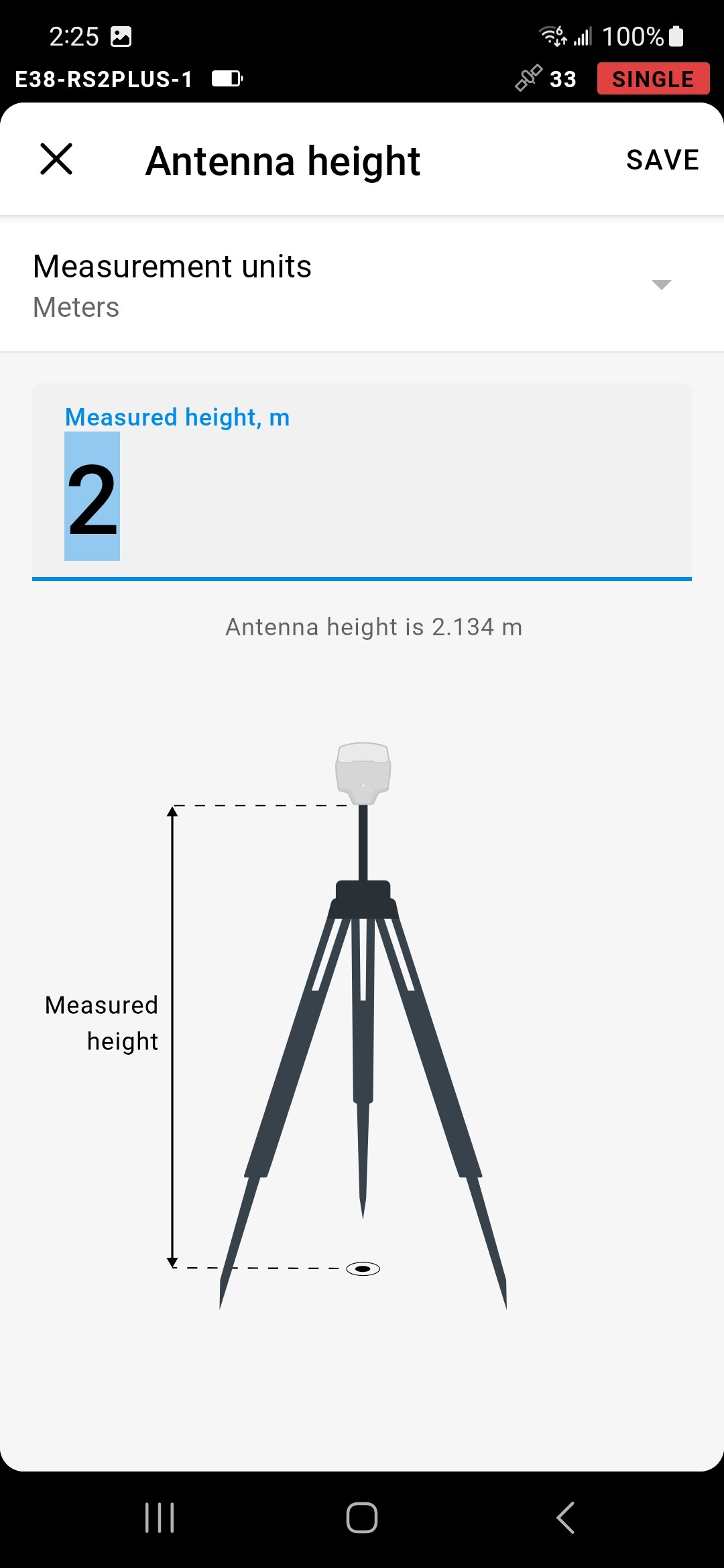
In Emlid Flow v 8.10 the drawings that are shown when entering the HI of the ARP are still primarily focused on showing the antenna height; and moreover, still not reflecting the absolute antenna calibrations (for only G1, G2, R1 & R2 frequencies) that were performed and are in the IGS database.
If it’s on the roadmap, when could we expect to see all of the frequencies’ absolute calibrations completed?
Trimble has beautifully illustrated what the absolute calibration values look like and in so doing, show why a single value of 0.134 m being added to the ARP is an oversimplification of what’s actually occurring/ impacting RTK heights.
We apply the offset to the physical antenna position (0.134 m) in RTK. The difference between it and the APC coordinates is much smaller than the precision values determined by the RTK technology. So, these settings provide accurate coordinates in RTK.
For post-processing, antenna calibrations are automatically applied in our Emlid Studio software.
Thank you very much for your reply <props and cheers!> and for making this important distinction: that Emlid Studio automatically applies the .atx antcal information; e.g., C:\Program Files\Emlid Studio\resources\igs20_2247.atx; or C:\Users\V. Kelly Bellis\AppData\Local\Emlid\Emlid Studio\resources\igs14_2247.atx; however, I’m unclear on which reference frame gets chosen for the user and where they’re given notice of Emlid Studio’s automated choice? Could you say?
In regards to RTK and Emlid Flow, how have the differences been determined and have they been published?
My RTK tests are detailed in my article, a draft of which that I shared with Liudmila Slepova yesterday with the subject line: “20230804 draft of story - PRELIMINARY - Pioneering Affordable GNSS Surveying Equipment”, sent at 8/4/2023, 8:01 AM UTC-4
Please note I have since revised it by quoting your helpful information on page 4, and have inserted it into the first paragraph.
Emlid Studio provides the results in the datum of the base station coordinates you enter. You don’t set the datum directly, so it’s not specified in the output.
The RTK technique allows you to get centimeter-level positioning accuracy. If you’re interested in the receivers’ positioning specifications, you can find the datasheets in our docs.