Hello,
I’m not new to data collection using Emlid, but I am new to utilizing coordinate systems, as well as importing CAD files.
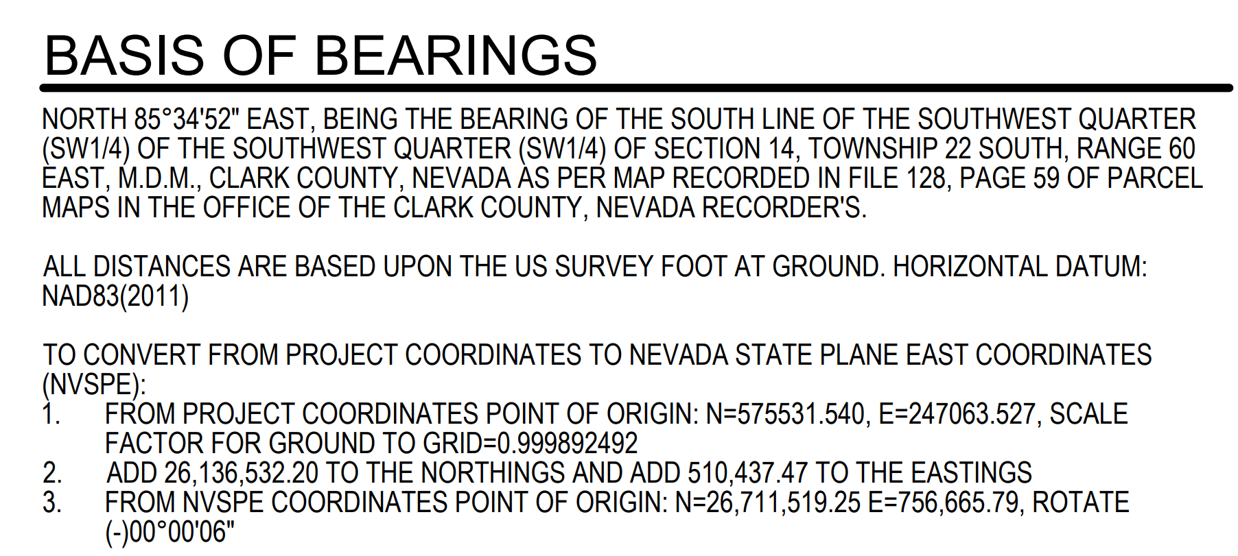
I’d like to use CAD files of my civil IPs but the coordinate system they use is typically custom. They do provide control points as well as a “basis of bearings”. For example, the “basis of bearings” for one of the plan sets is attached.
Is it possible to create this custom coordinate system in Emlid Flow using this description, or do I have to use localization from the control points that the engineer provided instead?
Long story short, I’d like to start using CAD files in Flow, but I don’t know how to get the correct coordinate system, or the best way to do so.
Thanks in advance.