I will begin by operating the Navio before LidarLite. That sounds more complicated than Pixhawk.
If someone already uses I2C, I would like to know how.
I will begin by operating the Navio before LidarLite. That sounds more complicated than Pixhawk.
If someone already uses I2C, I would like to know how.
Hi,
Have tried Lidar I2C setup and PWM setup as per the ArduCopter docs.
Neither produce any sensible output in MissionPlanner as one would expect from a Pixhawk setup.
I checked for the presence of the Lidar on I2C device bus and it was at address 60 where it should be.
It disappeared when unpluged and re-appeared when plug in again.
So I guess the sensor is not supported.
Can any of the dev team comment?
Regards,
Martin
Hi,
I’m replacing my ArduCopter auto pilot hardware with a Navio+
All ok until I try to add a Lidar Lite as an altitude sonar on the i2c bus.
The Lidar works fine tested with my Arduino based sensor system (other project).
But it will not read correctly on a working Pi 2 using your real time LINUX kernel even when Navio+ board is removed.
When I try the Lidar on a standard kernel on an identical Pi2 with a standard test program the Lidar works perfectly.
When I read the Lidar with Navio+ installed using the standard Linux kernel it also works perfectly.
When I use a standard kernel on the original Navio+ and Pi setup the sensor works perfectly.
Is there a bug in your real time Linux kernel?
Thanks for you time.
Regards,
Martin
Hi,
So I can get the Lidar Lite working with the standard kernel.
But now the ArduCopter will not start with:
Raspberry Pi 2 with BCM2709!
sh: 1: pigpiod: not found
sh: 1: pigs: not found
No pigpio interface for RCInput
Unfortunately the suggested fix for this is to use the real time kernel.
Oh dear. I’m a bit stuck now.
Any help appreciated.
Regards,
Martin
Hi Martin,
Most likely it is the I2C speed, we set it to 1MHz, by default it is 100KHz. Probably Lidar can’t handle it.
Ah ha,
Yes that looks likely given the random nature of the readings and responses.
Is the ic2 speed set in your real time kernel image or can I alter it from my end?
Regards,
Martin
You can alter it in the etc/modprobe.d/i2c.conf . Try setting it as high as Lidar will allow. We have it so high for a reason - PWM out, ADC and baro are on this bus and we wanted to keep bandwidth high. Please test with caution.
Hi,
A quick correction for the first post.
The Lidar lite i2c address by default is 62 not 60 as my fat fingers typed.
Martin
Hi,
After some bench testing of the LIDAR here are my initial findings, please excuse any typos:
Linux image used:
Linux navio-rpi 3.18.9-rt5-v7+ #1 SMP PREEMPT RT Thu Mar 26 10:31:34 UTC 2015 armv7l
ArduCopter, compiled as per standard Emlid cross compile procedure:
ArduCopter V3.3-dev (f486dd46)
Free RAM: 4096
FW Ver: 120
Lidar sensor:
Pulsed Light
LIDAR Lite Manufacture date February 2015
Hardware:
Raspberry Pi 2 Model B 1GB
Navio+
Connection type:
I2C standard connector to Navio board connector via a Pixhawk I2C splitter.
All sensor hardware and connections pre tested using an Arduino based test rig.
No issues reported on test rig.
Power source: USB lead.
Test target:
Natural plywood ceiling at approximately 1 metre above test bench, inclined at 22 degrees to the horizontal.
Sensor fixed position on bench.
Natural ambient lighting day time.
Test timing and procedure:
Each run at least 5 minutes on the working tests (200 & 100kHz).
Sensor tested with standard Pulsed Light test program to check sensor before each test.
ArduCopter connected to local MAVPROXY (latest version from MAVProxy)
and remote Mission Planner (1.3.30 build 1.1.5648.36304)
Sonar sensor setup via Mission Planner as TYPE 3 (APM2PulsedLightI2C)
RNGFND parameters left as default apart from:
RNGFND_MAX_CM 4000 centimeters Maximum distance in centimeters that rangefinder can reliably read
RNGFND_MIN_CM 20 centimeters Minimum distance in centimeters that rangefinder can reliably read
RNGFND_TYPE 3 0:None 1:Analog 2:APM2-MaxbotixI2C 3:APM2-PulsedLightI2C 4:PX4 What type of rangefinder device that is connected
Results:
I2C bus speed: 1MHz
random sensor readings of unlikely distances
I2C bus speed: 500kHz
random sensor readings of unlikely distances
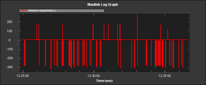
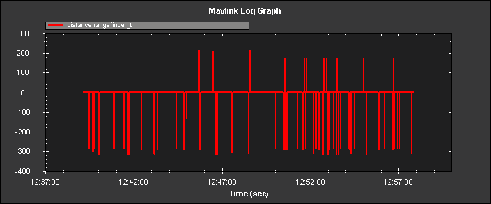
I2C bus speed: 200kHz
Mainly steady sensor readings of 1.00 +/- 0.03
Ocassional random outliers see graph
I2C bus speed: 100kHz
Mainly steady sensor readings of 1.00 +/- 0.03
Occasional random outliers see graph
Other results:
Hardware required power cycle after failed tests.
End of test results.
Hopefully that will provide a starting point for anyone trying this sensor.
Over the next couple of days I will perform more tests on the copter hardware for real. With the I2C bus power from a separate BEC with a basic ripple filter on the power rail.
Regards,
Martin
Hello @MartinSnaith
I’d like to look into the issue and there’s a couple of questions I need to ask.
I recall people had been struggling with I2C Lidar Lite connection on the LIDARs manufactured prior February 2015. I assume that’s not the case, right?
The issues you’ve told us about are random readings if I understand correctly. That doesn’t happen on an Arduino board at all, does it?
The issue might have something to do with the power supply as stated here:
I2C
The I2C lines are 3.3v. They’re setup for 3.3v and 5v operation (5v is converted to 3.3v and the sensor has an interal 4.7K ohm pullup resistor). If you’re using a 5v system with only our sensor on the I2C then the 4.7K pullup may be adequate, however if you have multiple sensors on the I2C you may want to use a lower resistance pullup.
and here:
Is there anything that can affect the accuracy of LIDAR-Lite?
If it is operated at too low a voltage, the power regulation may not be able to maintain the proper operating voltage for the Signal Processing Core or the laser may not be able to operate at peak efficiency. And, of course, attempting to take measurements beyond the maximum operating range of the sensor will also result in erratic readings.
We do indeed have multiple sensors on the same bus.
The other is I2C speed as you’ve discussed above. LidarLite operates at 100Khz mode only (I used the datasheet as a reference).
It can be connected to an I2C bus as a slave device, under the
control of an I2C master device. It supports standard 100 kHz data transfer mode.
Have you tried to launch the RFIND_test? It might be of some help.
The driver itself looks a little suspicious, though. I’m particularly concerned with a timeout right inside the read method.
  // kick off another reading for next time
    // To-Do: replace this with continuous mode
    hal.scheduler->delay_microseconds(200);
    start_reading();
I suppose the driver is a work in progress and needs some tuning. I don’t have a LidarLite at the moment, so I can’t fix it right now.
Hi George,
Thanks for your interest. Here’s a quick reply to some of your questions.
GS:
I recall people had been struggling with I2C Lidar Lite connection on the LIDARs manufactured prior February 2015. I assume that’s not the case, right?
MS Reply: Yes you are quite correct the ardupilot page at:
warns of the manufacture date issue. The Lidar I used has the correct label and according to Pulsed Light it’s the latest version of the current series.
Interestingly enough there is a new version of the lidar lite which is due out now, I have one on pre order. It promises improved I2C.
“LIDAR-Lite I2C communication will now operate at 100 kbits/s or 400 kbits/s.” See: http://pulsedlight3d.com/products/lidar-lite-v2-blue-label
Might I suggest that any serious investigation at your end is performed on the new version, when these issues may well have been solved by Pulsed Light themselves?
MartinSnaith:
No issues reported on test rig.
GS:
The issues you’ve told us about are random readings if I understand correctly. That doesn’t happen on an Arduino board at all, does it?
MS Reply:
I ran long test cycles with the Lidar on my Arduino test rig to characterise the sensor before use on the other project and did not see any of the rogue outliers.
There was a small variance in the individual readings and some surface variance but that’s to be expected. The rogue outliers are characterised by single large positive and negative values that are
way outside 3 sigma of the expected readings.
GS:
The issue might have something to do with the power supply as stated here:
The I2C lines are 3.3v.
MS Reply: It is possible. However the Arduino boards I use at present are UNOs and are run off the USB supply/USB connection (5 volt) when under bench test. Or at 11.1 volt Vin when on a copter.
Both cases behave the same.
GS:
Is there anything that can affect the accuracy of LIDAR-Lite? “Multiple senors on the bus.”
MS Reply: Again a possibility. The Arduino setup used for the other project has Maxbotix I2C sonar attached in addition to the LIDAR Lite. No rogue outliers seen.
GS:
The other is I2C speed as you’ve discussed above…
MS Reply: Yes it does look most stable at 100kHz.
GS:
Have you tried to launch the RFIND_test? It might be of some help.
MS Reply: Good idea I’ll try that in the next couple of days.
GS:
The driver itself looks a little suspicious, though. I’m particularly concerned with a timeout right inside the read method.
// kick off another reading for next time
// To-Do: replace this with continuous mode
hal.scheduler->delay_microseconds(200);
start_reading();
I suppose the driver is a work in progress and needs some tuning.
MS Reply: Yes the driver does look rather simple.
My Arduino rigs use an ACK/NACK rather than a timeout.
For example, taken from the Pulsed light git repository:
uint8_t nackack = 100; // Setup variable to hold ACK/NACK resopnses
while (nackack != 0){ // While NACK keep going (i.e. continue polling until success message (ACK) is received )
nackack = I2c.write(LIDARLite_ADDRESS, RegisterMeasure, MeasureValue); // Write 0x04 to 0x00

delay(1); // Wait 1 ms to prevent overpolling
}
byte distanceArray[2]; // array to store distance bytes from read function
// Read 2byte distance from register 0x8f
nackack = 100; // Setup variable to hold ACK/NACK resopnses
while (nackack != 0){ // While NACK keep going (i.e. continue polling until sucess message (ACK) is received )
nackack = I2c.read(LIDARLite_ADDRESS, RegisterHighLowB, 2, distanceArray); // Read 2 Bytes from LIDAR-Lite Address and store in array

delay(1); // Wait 1 ms to prevent overpolling
}
GS:
I don’t have a LidarLite at the moment, so I can’t fix it right now.
MS Reply: I’m tempted to put a simple outlier filter in the driver for now as they are easy to characterise.
One could use a Kalman filter but that’s a bit over the top in this case.
However I’d wait for the new version were I you.
Once again thanks for the interest George.
Regards,
Martin
Lucas de Marchi (one of the core APM developers) suggests trying to integrate the Linux kernel driver that’s already been written and tested. In order to use it with APM one needs to write a simple shim driver. There’re some issues that need to be resolved, i.e. sensors’ synchronization but the attempt is definitely worth a try. Are you willing to undertake this task? As of today, I still don’t have a Lidar Lite but I’m sure APM developers (including myself) will help you out for sure if you’re stuck.
Hello,
does anybody know how to connect lidar v3 via pwm to navio2,
with pixhawk we use the AUX pin 6 and 5, what are the alternatives in navio2?
Hi @husseinhamadi.020419,
Pixhawk uses its PWM driver for reading PWM input, but unfortunately, we cannot do this on Navio2. If you don’t want to connect your lidar to Navio2 via I2C, you can try to use the analog input. You need to change RNGFND_TYPE parameter from 5 (PX4-PWM) to 1 (Analog). Take a look at this class.
This topic was automatically closed after 27 days. New replies are no longer allowed.