The base station send via UART @ 57600 with a 3dr telemetry to the rover station, the rover station receive via UART the base correction. so until here everything is ok.
Now i want to output nmea strings via UART, i set the same baudrate of the input (otherwise the rover doesn’t receive tha Base correction) but if i read (via Arduino) the serial output into the rover i see nmea plus the base correction packet… does anyone have somethings to filter only the nmea strings??? i also tried to capture only what the rover write into the tx pin of the uart but it doesn’t work
And than why if i modified too much settings sometimes will reach doesn’t work anymore(i think that comes from Intel edison)? every times i have to reflash firmware and so on…
Thank you so much
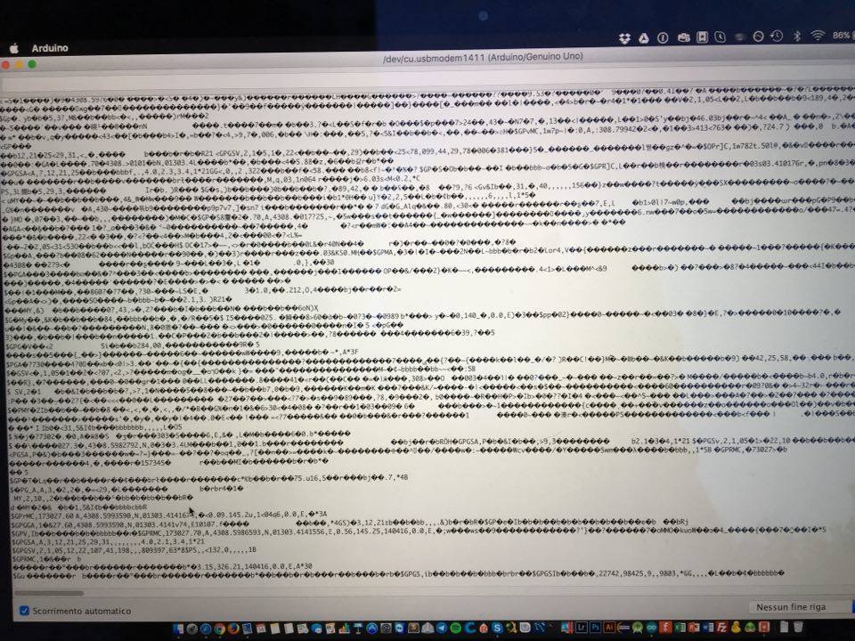
i upload an image where you can check what i receive from the serial of the rover… in other tests i reach better results but usually i receive a lot of data that i have to filter
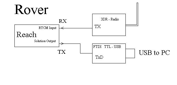
“Now i want to output nmea strings via UART” which one, Rover? where to? (see my drawings)
" but if i read (via Arduino) the serial output (from where?) into the rover" what serial output? why read to rover? send?
Did you do similar thing what I did:
At Rover side: I get RTCM from Base and send output solution (nmea or llh) to a PC. No problem with that.
There is no need to filter anything, because it is properly separated.
I did not change/touch at all the baudrate on the rover send line.
Working and changing to much makes the device unstable, I have flashed at least 15 times my both devices, now, since two days, it is stable…till the next time.
If your device shows strange things, you better flash…
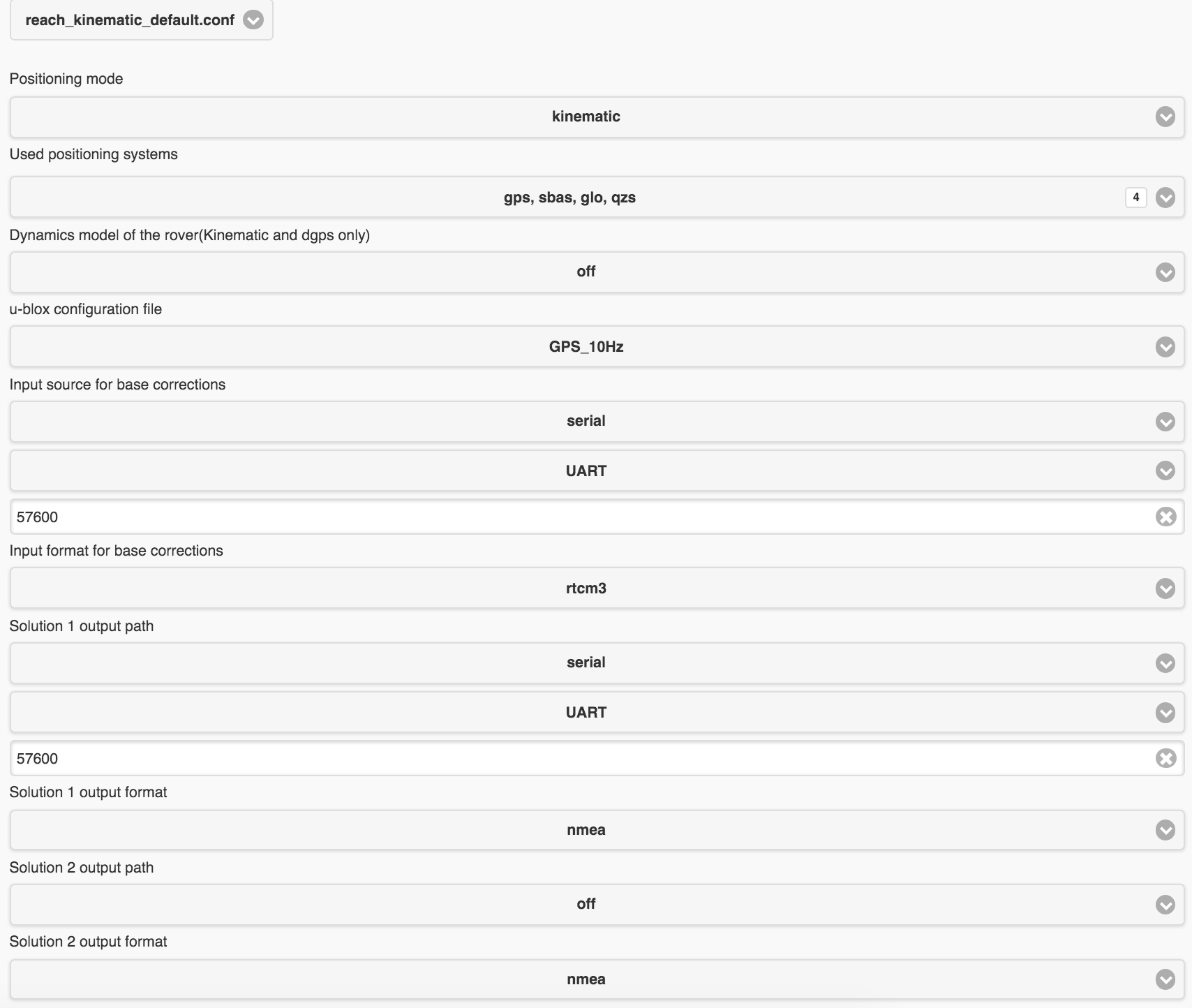
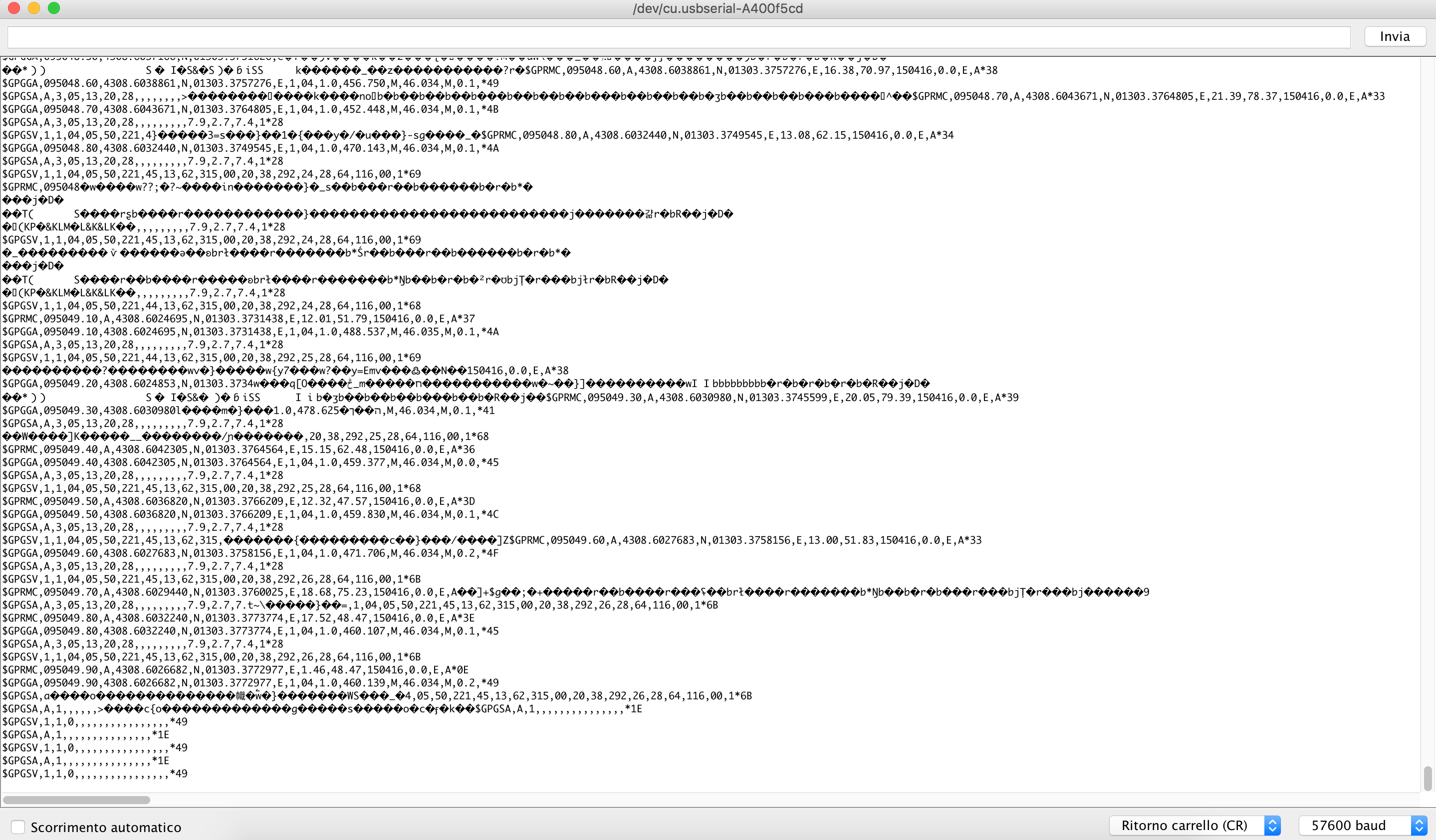
This is the result that i get today, i make the connection as you described with an FTDI
you can check both the result and the configuration of the rover
Well, it seems that there is some fault with the way you connected FTDI to Reach. My guess is that you did not connect the GND line. See here for the DF13 pinout.
ok, but to the ftdi i only connect the TX Pin of Reach, and i connect everything to the 3dr telemetry so 5V and GND are connected to the telemetry but not to the FTDI where i connect only the TX


 thank you so much