


The single base point was pulled from Google Earth. They don’t need global accuracy, just relative. All points are relative as positioned in a CAD file. The only other thing I mentioned was that if the site was built substantially different than the CAD file they would get these errors, but that is not the case according to the CAD when compared to an aerial because the CAD is an asbuilt.
What is benefit of extracting coordinate from Google Earth? If that is the case I would have just averaged the base coordinate for 10 minutes or so and then ran RTK. Eliminates possibility of error when manually entering.
How was the CAD derived and ultimately aligned to WGS84?
I am assisting remotely from another state and it was allot easier to send them a package of data ready to go rather than trying to train in all aspects or GPS, surveying and control theory. One piece at a time.
The CAD was aligned in QGIS based on a “localization” method. The point is that for what they are doing they don’t need to be globally accurate and already have the majority of information in CAD. Their task is to be able to asbuilt and do some simple design to field stakeout. All on an individual site relative basis.
I am by no means a master in this realm which is why we are on this and the DroneDeploy forum so I am learning a few things along the way as well.
2 Likes
Understood, we are all here to learn! I suspect however the source of this error may very well be in the georeferencing of the CAD file in QGIS. I align CAD regularly in ArcMap and also QGIS. It is always a fickle beast. Prior to Emlid I would align to aerial data or our Trimble GPS collected references. All methods created inaccuracies that were clearly evident back out in the field when verifying our maps/data by a consistent XY shift. This makes me ask if the other points were off by a similar distance and direction?
Would you mind describing your localization method in QGIS? We may be able to improve our workflows for this type of task as this is becoming increasingly more regular in my jobs.
1 Like
https://www.qgistutorials.com/en/docs/3/georeferencing_basics.html
I still maintain the fact that georeferencing or a correct global coordinate does not matter in this scenario. They have an asbuilt survey collected by a professional land survey with other gear so the points as shown in the CAD should be more accurate than 3cm (0.10ft). Everything beyond that is relative.
My process may be more familiar to you all as georeferencing, but it is done using known control points (GCP’s as referenced in the QGIS plug-in Georeferencer) and georef/localizing the aerial according to those surveyed control points. That map is then brought into CAD and the linework is run through an alignment routine to get it on the same basis as the georeferenced image. This can be done with a standard image or a geotiff from a drone survey. We do this regularly for design-build jobs when we have nothing but a couple of vertical benchmarks and tie-in within 5cm. Even better with our GPS localization.
2 Likes
Did you georeference the CAD to an aerial in QGIS? The same aerial of which you derived the base coordinate?
Correct my friend. The other way to do it if data is available is to import the Google Earth image directly into CAD, but sometimes that does not work so well and may be an older version of the image. Most of the time it works fine though. then you can run the alignment routine, but I have never compared its precision against Geo in QGIS.
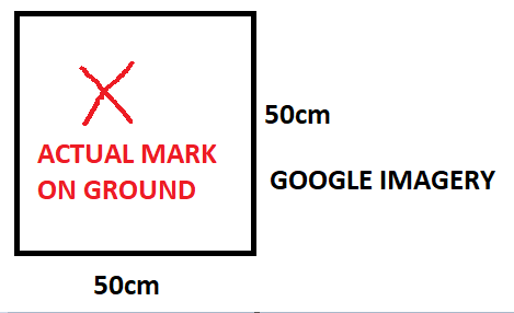
Is it possible the location of the base as marked in Google Earth was off? If I understand correctly the base position would only be as accurate as the Google Earth imagery. Even if the CAD was aligned to the Google Earth imagery you are relying on the “precision” of your mark. The resolution of the imagery is 50cm plus so to be very precise on your mark is inherently difficult.
My point is that what may have been apparent in the imagery and marked as the base point could be within that 50cm pixel resolution range and not exactly translated to that same mark on the ground when the base station was setup. So what may presume as relative between the CAD file and the base location can introduce “error” in the magnitude of the imagery resolution. When you georeferenced the CAD and then extracted the base you could have lost the true “relativity” between the two datasets in the pixel size.
1 Like
That’s a really good point because typically when I’m in this scenario I am localizing. I can look at a Google Earth image and pick points such as manholes fence post and other objects that are pretty reliably static and my localization comes in within 10cm every time, but without localizing this could be the problem. My method applies more towards having absolutely no information and setting an arbitrary elevation on one point. I can then adjust everything according to that point if I find a benchmark or something of that nature. I thought that this instance would be better because we had a survey as built. I didn’t realize that the resolution on Google Earth, even if updated, was that bad. Even with that, I am confused. I thought the point of a manual base was to override anything that was shot using distance from base?
2 Likes
It does but it was not overriding in this case because they were doing a stakeout rather than collecting data. The only localizing that was done was defined during georeferencing in QGIS.
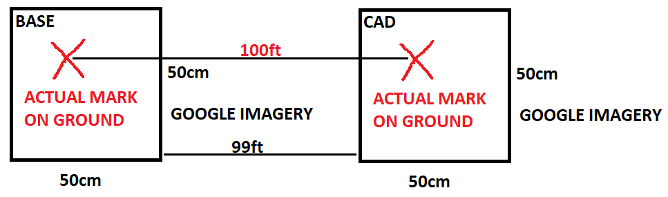
Back to my fancy paint drawing but because of the resolution of the imagery you may have affected the true scale of the project. What is actually 100 ft on the ground you may have defined as 99ft in QGIS. One would have had to collect a few common points on ground and CAD with the Emlid and then georeference the CAD in QGIS to the correctly scaled Emlid points.
1 Like
Gosh doggit. No localization! I guess I can try to do than in CAD to see if it helps, but I want to make sure the instable RTK isn’t the root problem…
3 Likes
Not saying this the problem but definitely a potential source of error! I am curious on the Emlid RTK side though to confirm…
1 Like
You trust Google !!! lol ! Google is not accurate : you could trust non uniform range from 0 to 20m
You dont have access to public orthophoto otter than from Google?
Here the state provides ortho and angle photos every1-2 years. (But no free NTRIP…  )
)
It’s not a matter of trusting Google Earth, but a failure on my part to understand that an arbitrary point setup was not possible in Reachview like it is in other survey systems and that entering a manual point does not function the way it is described in the documents. I now understand that the point needs to be exactly within a tolerance of what a CORS or 10-minute collection would be and that you can then use that point moving forward. This basically meaning that relativity is totally dependent on the GPS coordinates and not the information that you input.
1 Like
I will look for this. I was going to suggest a drone flight as this is something else I have had very good luck with, but here again using localization so it pretty much doesn’t apply to anything Reachview can do. Thanks for all the help!
This topic was automatically closed 100 days after the last reply. New replies are no longer allowed.