Is there any command I can run after installation to very that the NAVIO+ is working?
What is the best simple test I can run to verify that all the internal sensor are ok?
Is there any command I can run after installation to very that the NAVIO+ is working?
What is the best simple test I can run to verify that all the internal sensor are ok?
You have to download, build and run all the samples to test the hardware.
To download the samples run:
git clone https://github.com/emlid/Navio
cd Navio/C++/Examples
Then basically go into each subdirectory and run “make” to build them, then “.<program>” to run them, where “” is the executable name, usually the same name as the directory or main source file.
It’s documented in the “Navio for Developers” under each sensor type, e.g. IMU, Servo and LED, etc… See http://docs.emlid.com/Navio-dev/mpu9250-imu/ and following sections for other chips/sensors.
Most people do this when they suspect hardware problems. Otherwise it’s probably easier to just download and run the APM binary and go through the normal setup/calibration sequence there.
In the long term it’s a good point that there is a need for a single stand-alone test program on the Linux image. At least there will be a stand-alone Windows IoT image soon, which will just boot and have all tests available to run with a GUI. But that’s a few weeks to a month away yet.
Thanks for the answer.
I had already read in the documentation about these examples.
Sensors seems to work fine.
About the IoT image: Will it also run realtime RTOS?
Thanks!
It already is, with the same stable kernel as the rest of Windows 10/Server 2016. Windows always supported realtime process and kernel driver priority right back to NT 4.
IoT helps additionally by not being a “fat desktop” and supporting headless mode. In that respect it’s more like Hyper-V/Server Core than Windows 10.
Just one point to take into account if you test IoT; don’t be put off by the terrible graphics performance. Microsoft didn’t get around to finishing the GPU driver, so it’s software rendering in the current build. That makes the existing test apps (also without proper drivers) appear very “sticky”. That will all change.
Hi again!
I have not manage to have any success testing the Servo example.
In the documentation and drawings I’m not 100 % sure what the documentation mean about ’ To provide power to the servo rail plug your drone’s BEC into any free channel on the servo rail’.
I have mounted. a Battery to the power port. Shall I mount a new battery (BEC) into any free channel on the servo rail?
Before I do something wrong, is there any picture example that shows this more concrete?
Thanks again!
TG
Yes you need a separate 5v power supply (from the same battery), usually provided by a BEC circuit from a PDB (if you have one) or one of the ESCs. Some ESCs don’t have BECs (known as “Opto” to reduce interference).
It’s documented here:
http://docs.emlid.com/Navio-APM/hardware-setup-navio-plus/#powering-servo-rail
Specifically take note of the section:
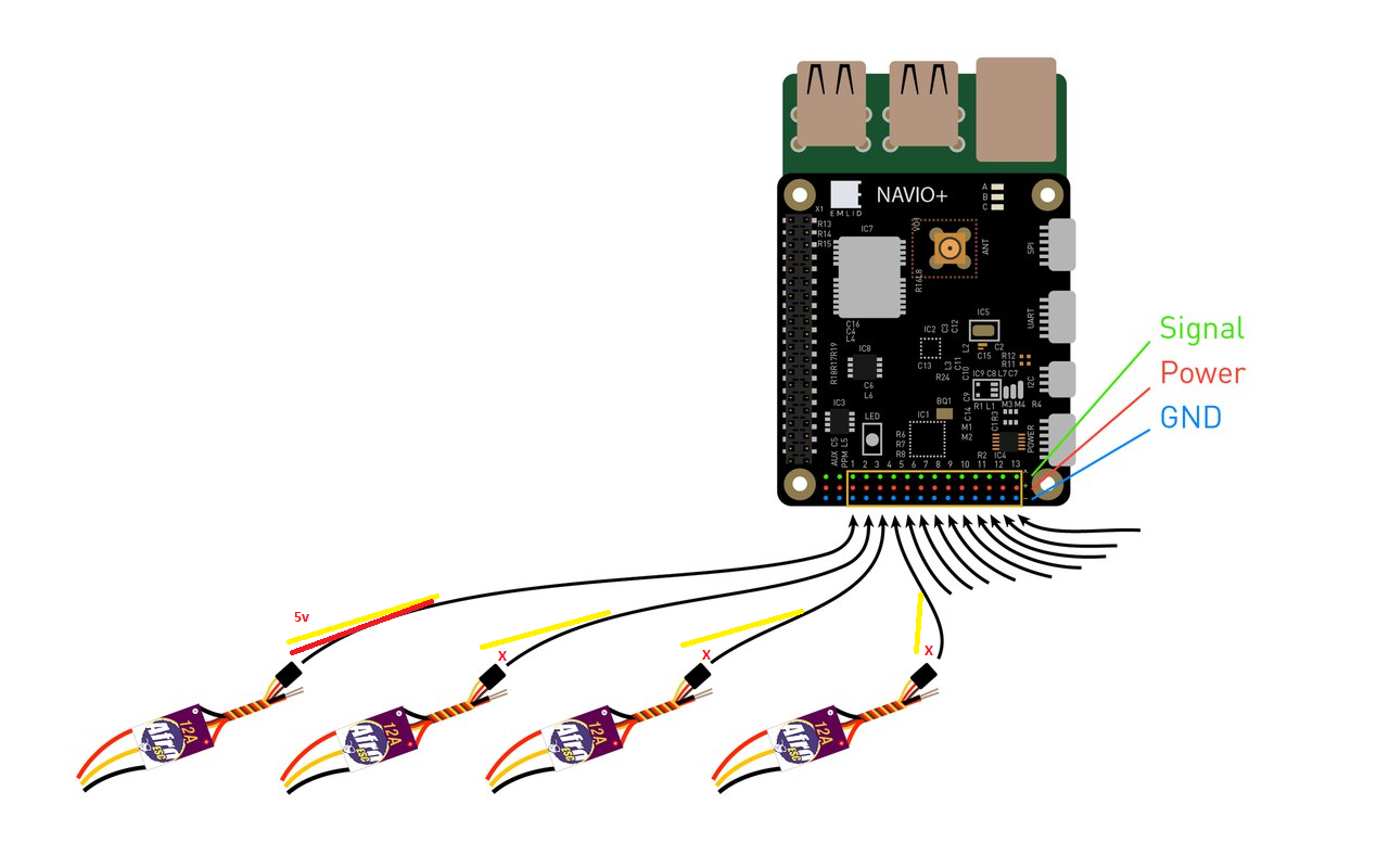
Only one ESC central wire should be connected to Navio+ otherwise BECs built in ESCs will heat each other.
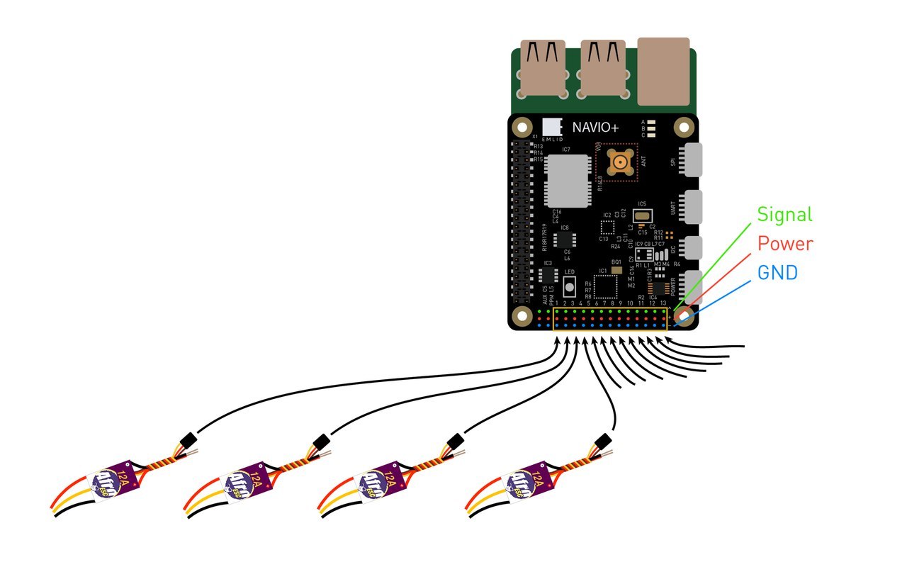
Basically, if all your ESCs have BECs, then remove all but one of the red wires from their servo connectors. That picture doesn’t show it. Just remove the wire by pushing a small screwdriver under the flap of the servo connector, pull it out the connector then tape back or heat shrink so it doesn’t short-out. https://www.youtube.com/watch?v=4Ri8i5ITI8o
When the power is coming from another source, for example I have a PDB and many quadcopter frames have PDBs built into them now, then you wire-up the 5v cables to a servo plug and plug that in any free servo connector, or AUX port.
It doesn’t matter which port on the servo rail the power goes into, just that only one power connector is used.
Here is a better picture: