I am in the same situation as Luccatiel without Radio communications at the moment so I am trying to get good relative positions based on post processing. I have followed the post processing tutorial and I have settup both rover and base to to single and recorded raw data with GPS and Glonas to 5 hz. During the test, I used the project survey tool within ReachView app to collect 4 waypoints which were some features on the field. For these features I measured the distance between each other. So after processing I could relate results with real measures.
What I really haven´t found how to do is getting the coordinates of the 4 waypoints I collected using the rover. I know I can export the project to shapefile while connected to the ROVER with ReachView but these coordinates are taken using only single mode. Is there something I am missing in the post processing so I can get also the waypoints with corrected coordinates?
For reachview collect function to be accurate, you need to have set it up in RTK mode. Meaning yo have a rover that is getting correction data from base or similar.
For post processing this function is no good.
Hello TB_RTK, Rick J, Bide, Luccatiel and all reach users,
Thank you for the comments. At the moment as I wrote before, we are without radio connection (which are connected to USB-OTG and they seem to be powered but I haven’ t found how to link them yet).
Record Base lat/lon/height and write it down to be used for post processing
Now in the post processing, I can pick any obs file to be used as rover or base as recommended by Bide Pro: [quote=“bide, post:2, topic:2658”]
When using RTKPost, just pick the .obs file that you want to use as the base and the other .obs file as the rover. The .*nav files can be picked from the unit that had the best sky view.
[/quote]
For this project I created a drive folder open to the public in which you can find:
-Raw data (ubx files for both receivers)
-Process images for each tab settings using the RTKpost. I did not include images of the RTKconv since it is straight forward process.
-Results images testing single, static and kinematic post processing modes
-Config files used for some of the tests
-Survey waypoints in shapefile collected using the survey tool with the rover receiver
Link to all above data is here: https://drive.google.com/drive/folders/0B_ehVYYUBf1PMU4wNVV3VlZpODA?usp=sharing
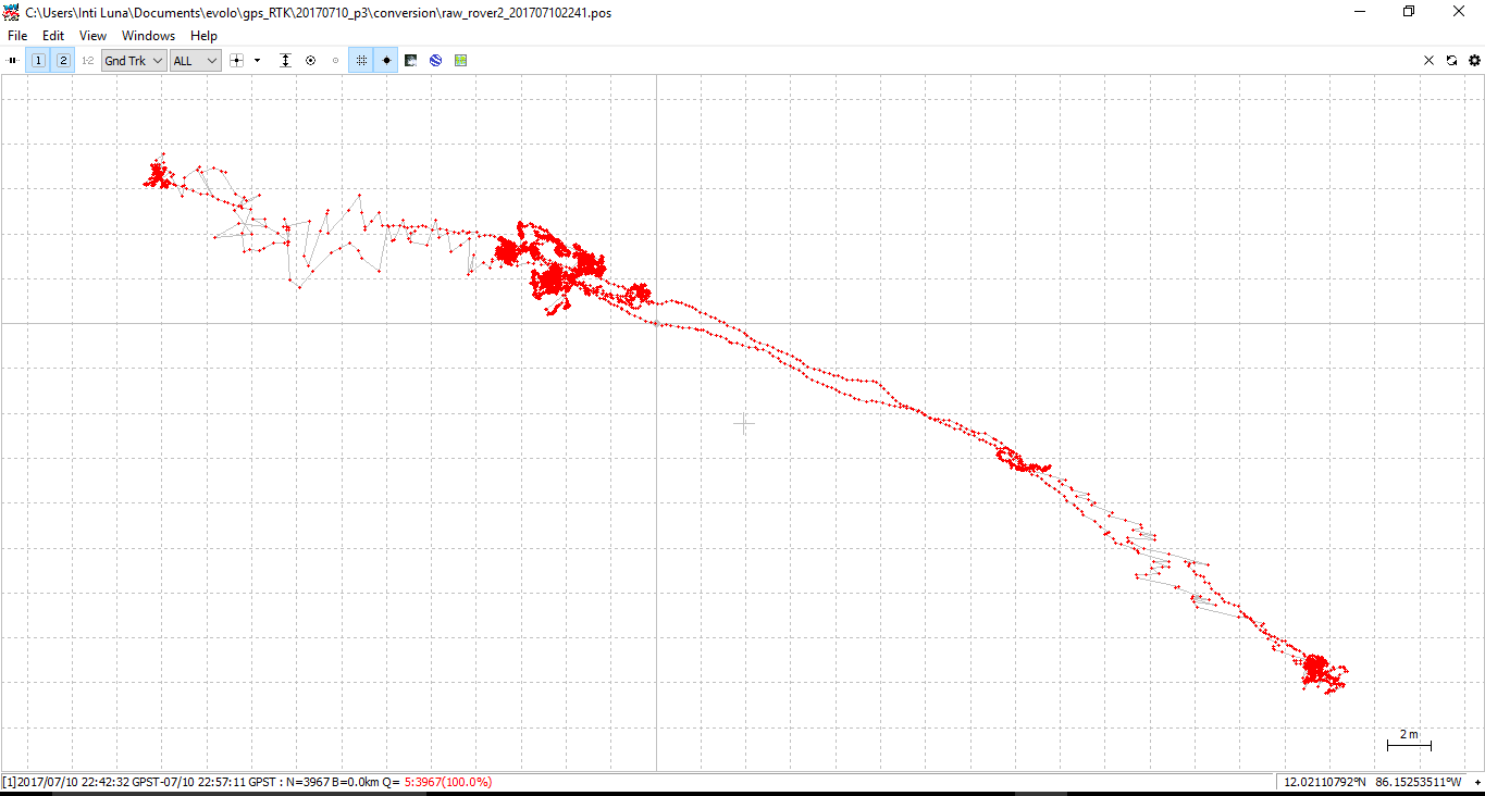
In general i got better results with kinematic configuration in the post processing.
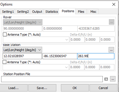
I entered base coordinates and heights manually (coordinates that I got using the receiver in single mode averaging for 2 minutes) in here:
I would like to get some guidance from Reach user with more experience and/or developer team to know:
if I doing a proper post processing and please let us know recommendations on how to improve it.
how to get the coordinates of the waypoints collected using the survey tool (corrected) after the post processing. Please notice that I already try to open with the RTKplot the pos.events and the plot only shows the reference point (base) but no other waypoints.
Thank you all for your help and time to explain simple things to a new reach user.
There is no automated way at the moment to extract surveyed points in post-processing. You can do it manually by locating them in RTKPLOT and clicking on “add waypoint”. Waypoints can be exported after that.
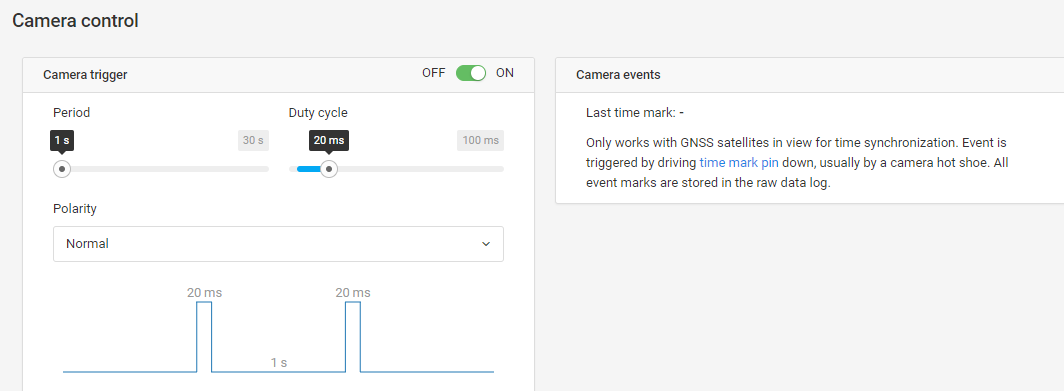
Thanks for the reply, It would be great to include this tool since at the moment I have several recorded points around my waypoint of interest and I am not sure which one is the correct. How about using the camera control to register events at the waypoints of interest. This would be a possibility, right? In that case, how to develop a trigger to record events? Do you know anyone who has done it before?
Here is what I can see under camera control in my reach:
I have read what is available in emlid docs: https://docs.emlid.com/reach/common/reachview/camera-control/
but I would like to have more information about it. It would be great if someone can make one, or show how to make one. I bet many people would be interested to learn about it.
I guess some sort of electronic puls, like 5-24v will trigger an event.
I might give it a shot on my “frankenstein” unit @igor.vereninov might provide me with the volt spec needed?
On a second note i notice puls or a really short shortcut might be better. Just a plain shortcut is to long in terms of milliseconds and with the result, it creates multiple events within that second that you used or held the wire connected.
Thanks both for the clarification on how to create an event mark. Now the question would be how to create that really short shortcut?. And speaking of frankenstein, i will show you my temporal settup tomorrow…
With regard to multiple events being triggered, try a search for “how to debounce switch contacts” One way is to wire in a TTL or CMOS IC chip with logic gates.
Just an interrupter will do the job. TTL is not using with flash triggering time mark : it’s only central pin + ground = same as interrupter. There is an onboard resistor in relay to the time mark pin.
Could you give some clarification on where the event is after you pull the time mark pin low? Isnt the log file a binary file (.UBX)? How to view these events since I can’t read .UBX file in text editor?
I was wondering what the ______events.pos file was for. That is what you are talking about righto?
Edit: I have 1 more question. I need to use the CUI version of rtklib for my particular use. Anyway to get the events from rnx2rtkp? Seems like only the emlid RTKPOST gives the event file?


