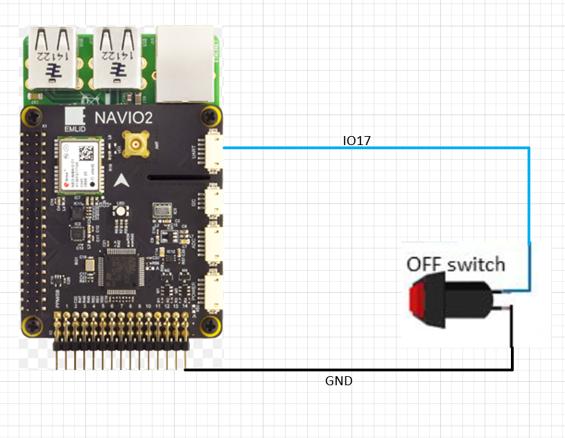
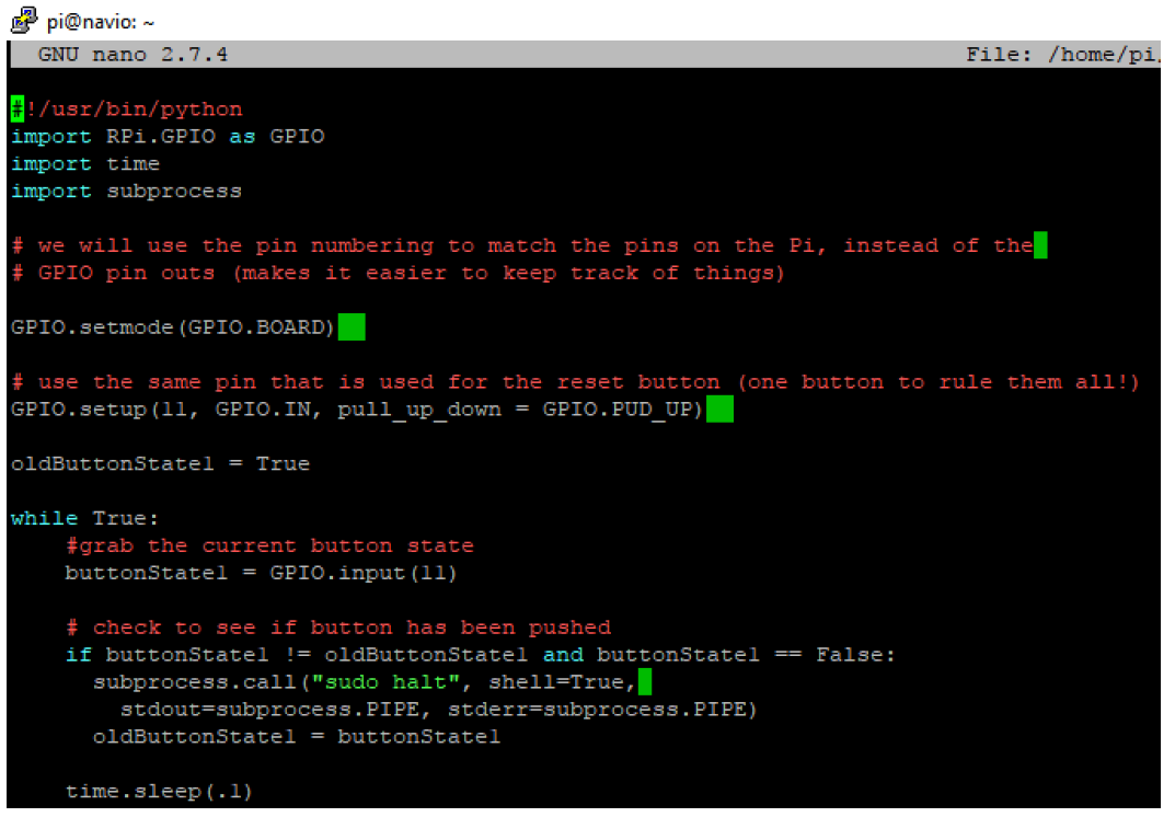
In the end regardless if the button is physically connected to IO17 via UART or not, running the python script immediately shuts down the RPI. Please help me understand the following below.
what is correct way to utilizes free gpio 17 and gpio 18 that are available on UART?
Are there any setting that needs to changed in navio2 or in GCS (Mission Planner) before these free pins can be used?
Where do i find the documentation on how to use free GPIO pins available on Navio2 UART Connector?
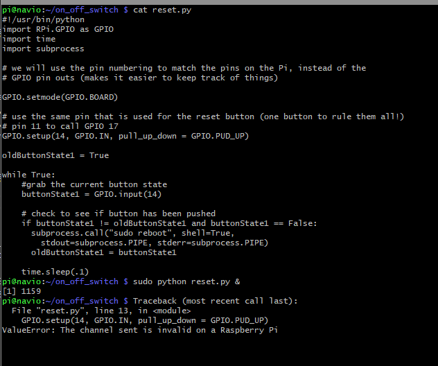
Why does RPI shutdown as result of executing the provided python script?
How do i fix this shutdown problem ?
i look forward to your feedback/answers. Thank you
i perfectly understand that its a option but i am using those PWN outputs for few other things. i would rather utilize IO17 or IO18 for OFF Switch via UART as its available. i look forward to hear more on this. thanks
pigs modes 4 w # set gpio4 as output (write)
pigs modes 17 w # set gpio17 as output (write)
pigs modes 23 r # set gpio23 as input (read)
pigs modes 24 0 # set gpio24 as ALT0
For this, it needs pigpio library installed and some other steps available on internet. However inorder to start running these commands it needs “sudo pigpiod” enabled.
I set pin to output and set it to 1 to see if it worked. Its still not outputting 5V.
→ I am probably missing same thing as you. Those RELAY_PIN stuffs on mission planner.
If anyone could help, that would be awesome. Thanks
i understand your frustration because its not clear anywhere how gpio stuff is setup specially for navio2. i did found a temporary work around for this that might work for you as well. Please follow steps below in sequence
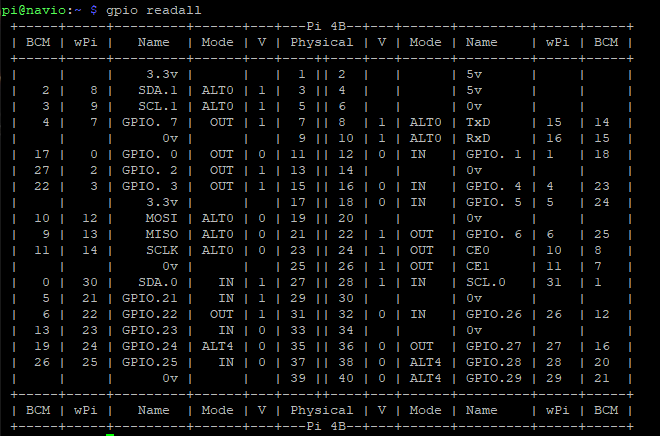
use the “gpio mode wPi# in/out/alt0” to change mode. for example physical pin 11 on pi corresponds to 0 on wPi so then command will be “gpio mode 0 in”.
you can also change the value(V) using this command “gpio write 0 1” and that should change V = 1 on physical pin 11.
lastly, the link below provides more information on how to use other commands. i hope this helps until emlid/navio2 people can provide some answers. The GPIO utility | Wiring Pi
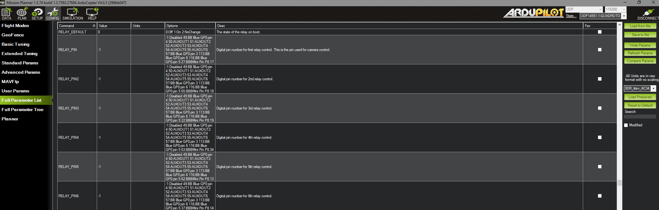
To set up a RELAY_PIN parameter in the Mission Planner, you should be able to change its Option to the pin number. In this case, you will need to insert 14. More details on relay configurations you can find in Mission Planner docs.
I don’t think you understood what i was asking.
“To set up a RELAY_PIN parameter in the Mission Planner, you should be able to change its Option to the pin number. In this case, you will need to insert 14.” SHOW ME HOW !
I have gone through the documentation as well as navio2 docs multiple times and it is no where clear how it must be done. This must be an indicator that your docs needs attention.
Forget the script above, is there even a proof/evidence that IO17 & 1O18 are accessible via UART connector like it is said in you docs, Please show test Case. At this point i don’t think you guys even understand your own hardware fully. i have provided/figured out so much technical information on my own and the only answers i get from you are should or could. Please Please and Please take this as negative feedback rather then criticism and i hope i hear some helpful information next time. Thanks