I’m starting to confuse myself.
As per the diagram, and by way of example can you tell me what measurements I would use in these scenarios:
Assume the distance from ground to screw is 1.0m for simplicity
What do I enter into RV3 for Base Ant heights?
Into AusPos for Ant height?
Into PPK software/ for Ant Phase Centre?
I think such an example would be handy in the documentation.
Thank you
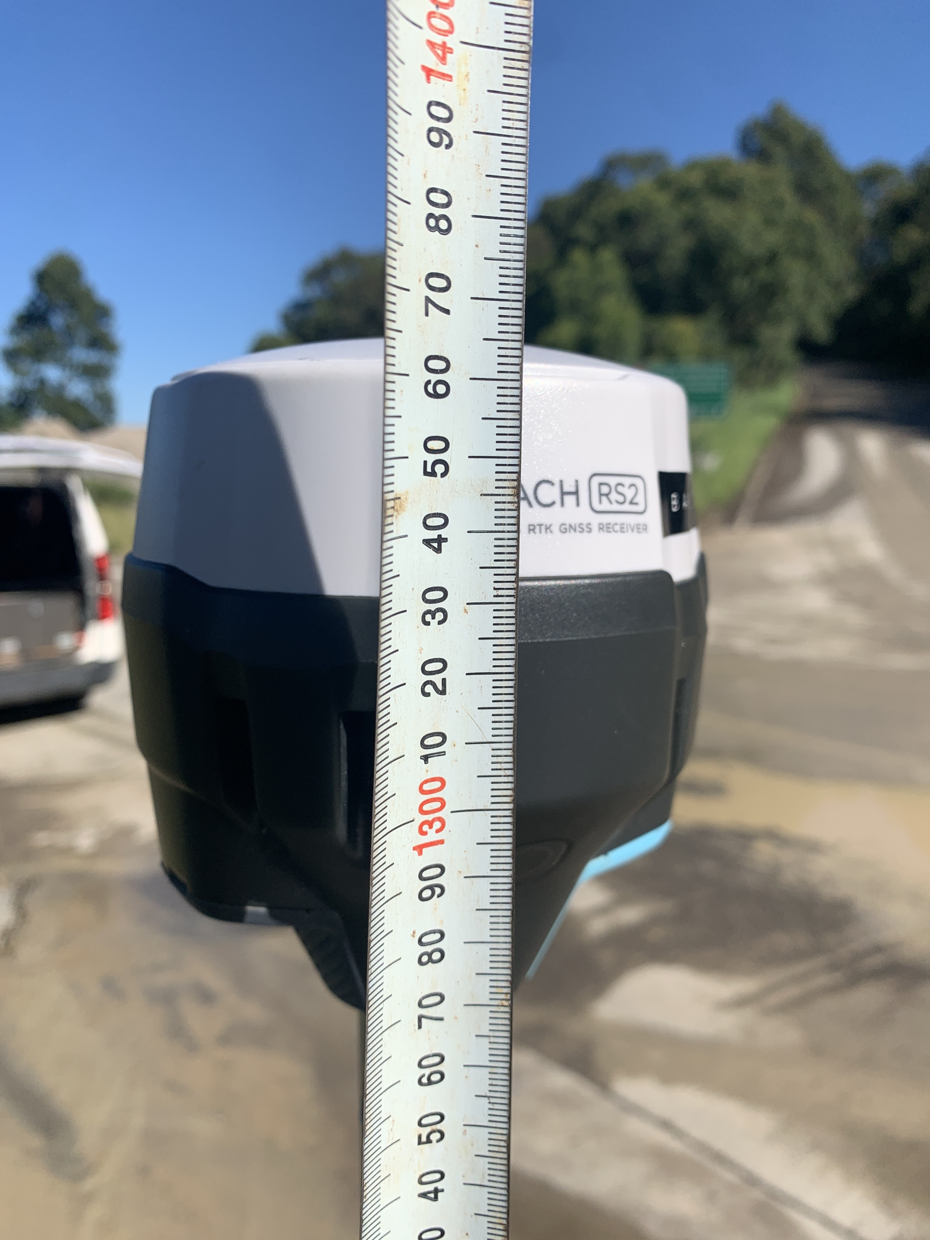
The change of colors is a part of the design only. 134 mm from the sketch you’ve sent is the distance from the bottom of the receiver to the GNSS antenna’s physical location inside it.
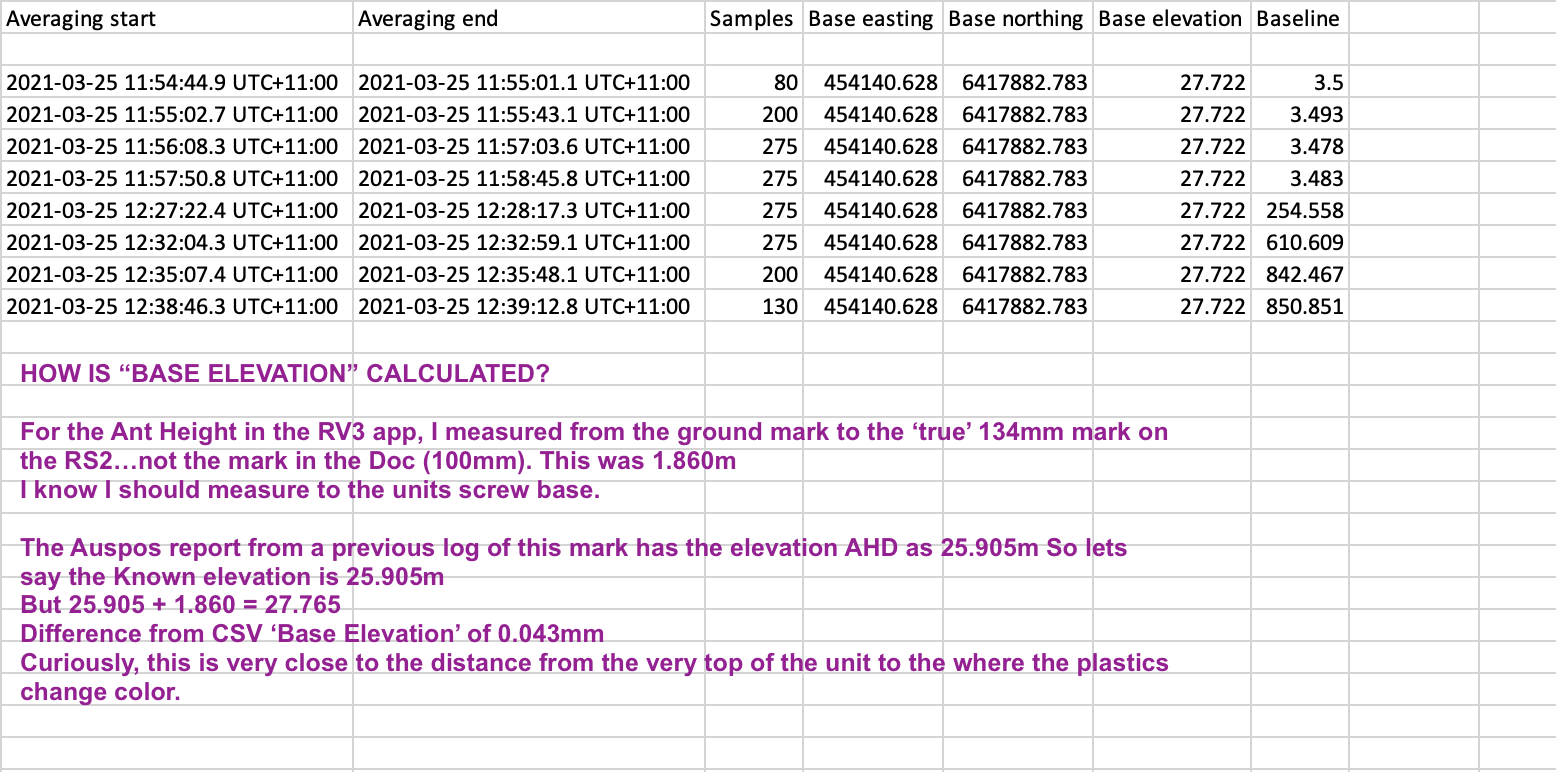
If you enter the base position manually, you will need to calculate the GNSS antenna’s physical location. To do it, add the pole’s height and 134 mm to the known base position on the ground.
When you average the base position, you get the distance to the antenna phase center right away. You don’t need to add any offsets for that.
The CSV file contains the coordinates the rover received from a base station. So, it should be the same coordinates that you enter on the base station unit.
In AUSPos and other PPP services, you will need to enter the pole’s height in the Height field and choose the EML_REACH_RS2 Antenna Type.
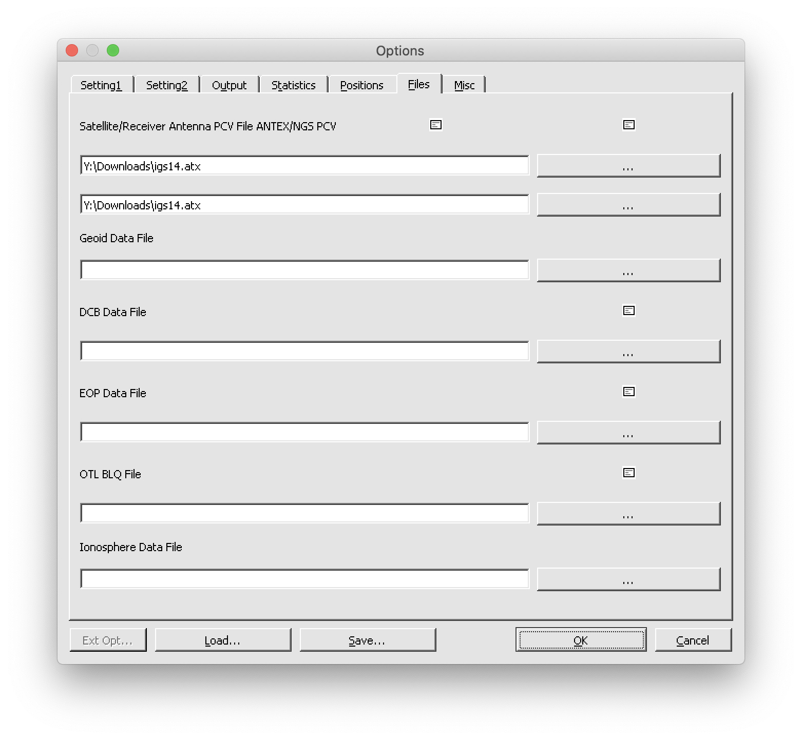
You can apply the antenna phase center value in RTKLib. To do it, you will need to upload the atx file. You can do it as follows:
Hi Kseniia,
So can you appreciate the confusion in the Emlid Documentation graphic depicting the 134mm dotted line? It looks like it is extending from the plastics color change.
In the RS2 image attached, if I subtract 134mm from 1362mm am I close to Antenna height? Because 134mm from the base of the unit puts it (Ant’s physical) there.
The igs14 link you provided simply takes me to the forum main page. I have tried to search the forum for igs14.atx but nothing of use comes up. Is there a more specific file location please?
Lots of neat info on here. We use to use the temporal products (EOP) when performing astro-observations with our Kern DKM2, Wild T2 and T3 theodolites.


