Received my Navio2 this week. Installed a telemetry radio and as I was removing the UART connector, the piece of plastic housing broke off. Now the cable is only seated to the pins and falls off very easy. I am not blaming the Navio2 in any way, I love this thing so far, and it was most likely entirely my fault that it broke. I don’t think I put all that much force when removing the connector, but these connectors aren’t always easy to get out sometimes. I may have removed it in a way it didn’t like.
how hard is it to re solder one of these connectors?
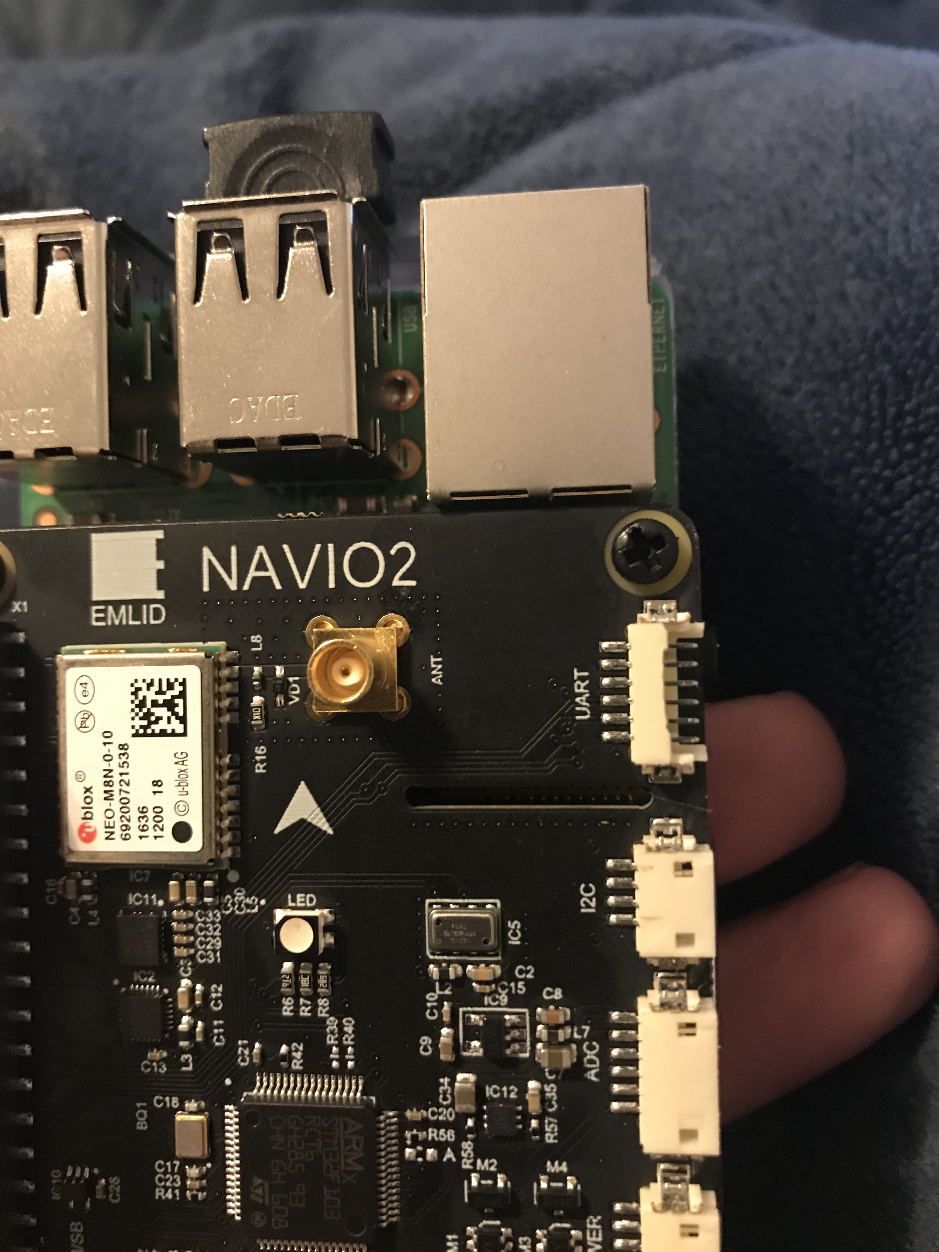
I may just electrical tape the UART cable in place, but I was wondering if anyone has ever broken and repaired one before.
i would de-solder the whole socket and solder the cables directly on the solderpads.
Needs a steady hand and a magnifying glass, but that would be the way i would go.
or you replace the socket. i think its a JST RM1.27mm but probably emlid can tell you
better which exact model they are using, they are a lot of different sockets out there
if you have an old power-board you could remove it from there
Well I guess this is going to be my first suggestion for Emlid to fix in the future. That area of the PCB has more room to 1) put the connector closer to the PCB edge so that cables can be removed easier. These connectors require downward force when removing the cables, and with it set so far in from the PCB edge, it makes getting that downward force to safely remove the cable from the connector a lot harder then it should be.
There is room on that area of the PCB for larger solder pads. This is a DIY board, and it is going to be inevitable that people will run into the problems I had, and will need to re solder connectors onto the board. It can be from accidents or even crashes in the air. I just looked at the solder pads and they are tiny and were soldered by machine, and its very hard for a human to solder at that small of a level.
The connectors used should be changed, These connectors are kind of made for “Plug in once and never remove it”. Not very useful on a DIY/Project board. I would think about moving to the connectors that proficnc uses on the PIxhawk 2.1; the JST-GH or whatever. Ditch the DT13 or whatever these things are called.
Hopefully I can rig up a solution. I may think about using a UART to USB converter and call this UART port a loss . That sucks on a board I paid so much for, and only had less then a week.
BE CAREFUL WITH YOUR CONNECTORS PEOPLE! They are fragile.
Actually I’m just going to solder the cable onto the connector permanently and just have a male lead on the end of the cable that I can then plug my radio into. Will look goofy having a permanently attached cable but whatever.
Emlid did a really nice job with the software and the rest of the hardware is awesome.
These are DF13’s and known to be a huge issue across all autopilot hardware that uses them. Never designed for multiple insertion and extraction. The plugs should be inserted with a finger backing up the connector and removed with a small screw driver in order to help avoid failure.
Latest DroneCode standard is a JST GH which is better. But sourcing and/or crimping them is not likely a DIY activity.
I miss the days when everything was on a .100 header.


 Anyone have any suggestions?