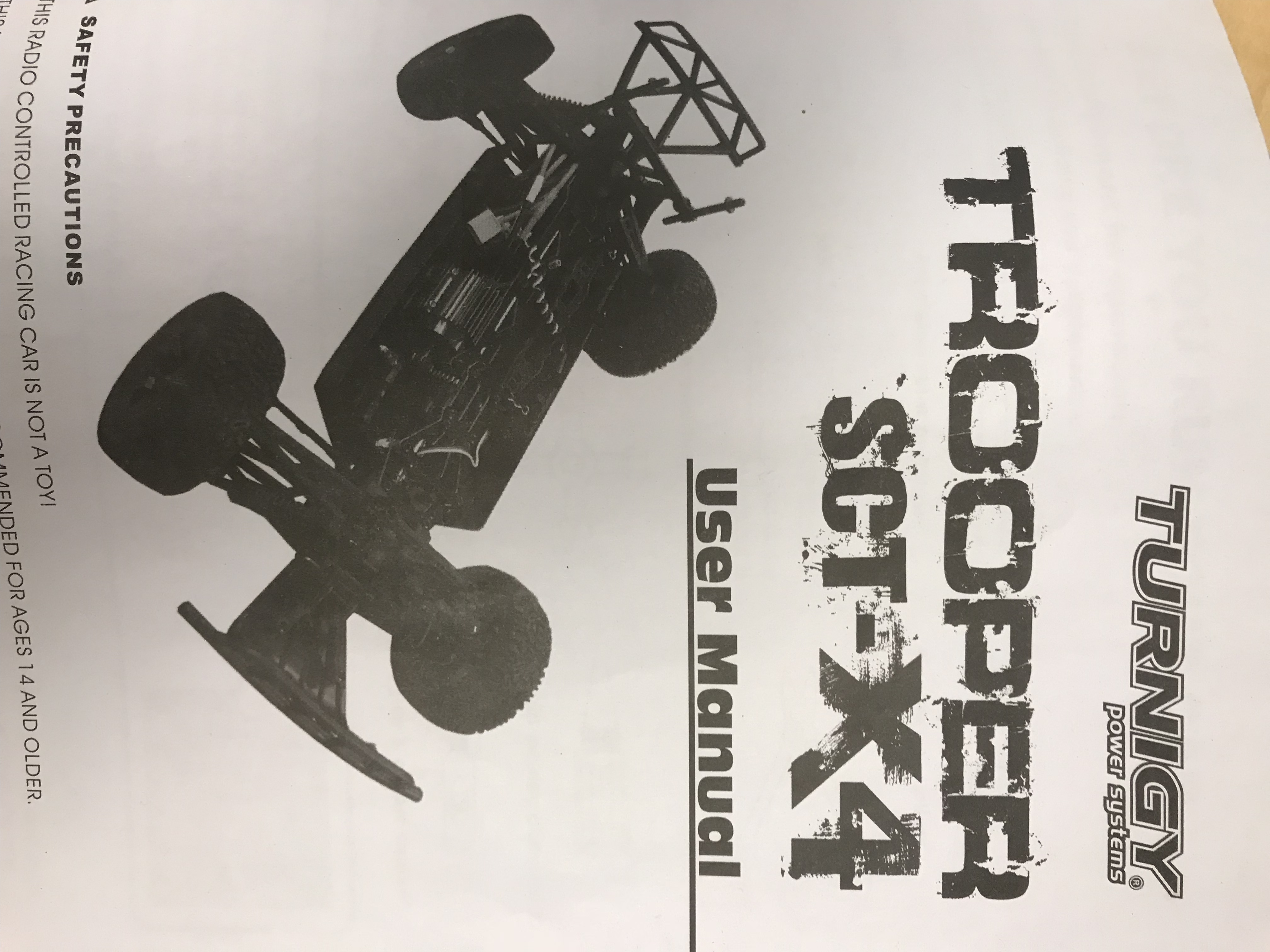
For Navio2-based Rover, I am using this example of Servo (Navio2/Servo.py at master · emlid/Navio2 · GitHub) for testing control of Servo and motor and got several questions. Just to give you some background, I am using Motor and Servo coming with Turnigy TROOPER SCT-X4 (images attached)
I have the following questions:
1). How do I provide power to the servo? I see a lot lot people mentioned using servo rail for powering the servo, but there is only one wire (brown+red+yellow) coming out of my servo. Is this the servo rail you guys mentioned? I thought this one is just for receiving PWM signal from the Navio2
2). How do I decide the duty cycle of the PMW signal for servo and motor? In other words, the value of SERVO_MIN and SERVO_MAX. You see in the instruction manual there is no specification for the motor and servo except something like the perceptage(%) in the programmable items list.
3). Since I am only running ROS on my Raspberry Pi and want to use that for controlling motor and servo, how do I do the calibration for the ESC? All instructions I found is about using RC for calibrating the ECS.
You connected servo and ESC the wrong way around. The yellow/white wire should be connected to the innermost pin on the Navio2 servo rail.
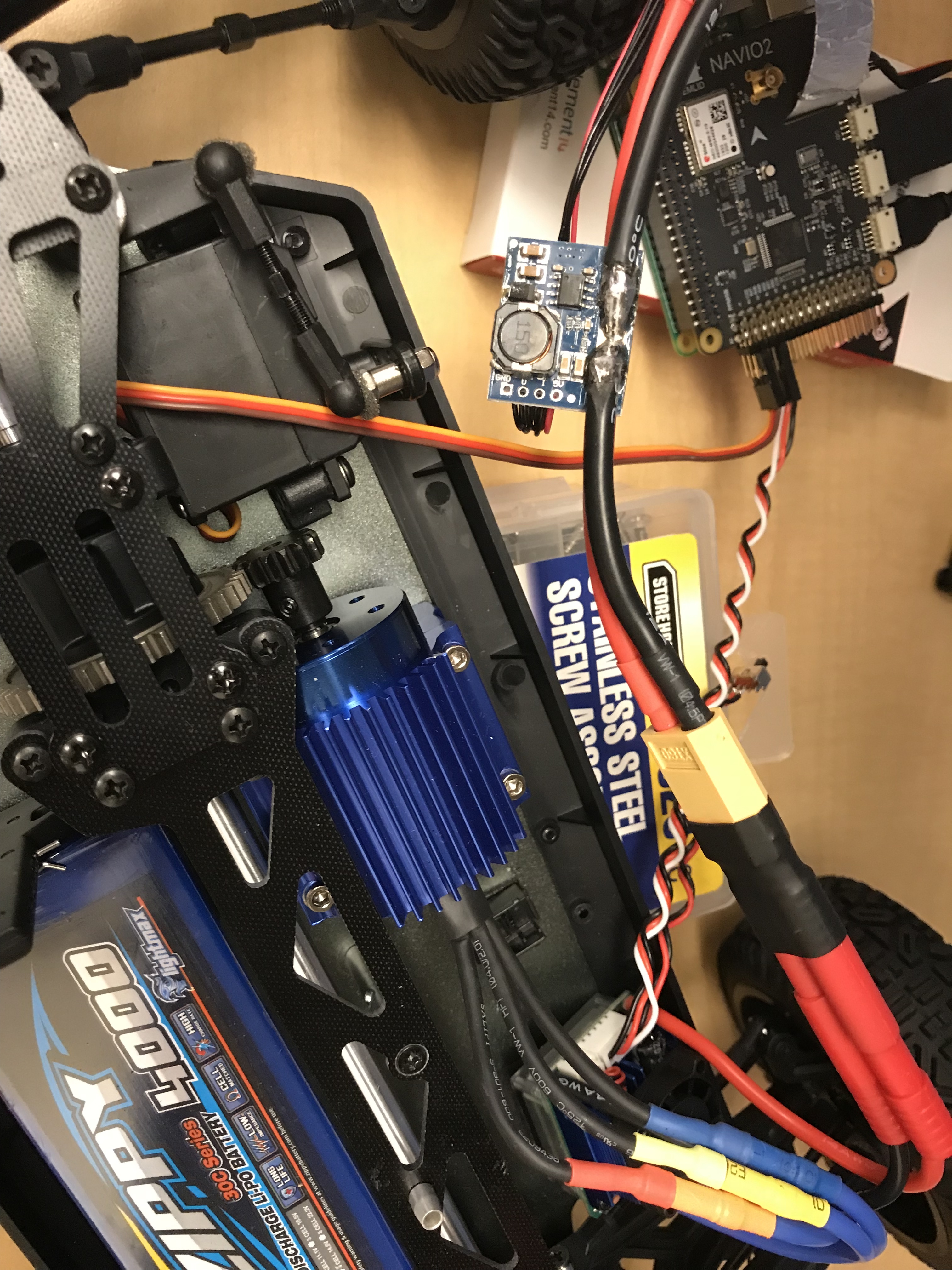
The ESC has a built in BEC that converts the lipo voltage to 5V/6V for servos and receivers. Read through the documentation of your Trooper again, many car ESCs provide 6V and the Navio does not like that. If it is 6V, pull the red wire out of the ESC and servo connector and use a double pin to connect them together. A thin piece of solid wire or such might work too. Isolate the connection afterwards.
RC PWM signals usually have a min/center/max of 1000, 1500, 2000us. Adjust your code, so the steering servo does not hit any mechanical limits. The Troopers frontwheel dogbones also like to fall out, if the steering is at max angle. To prevent that, put something soft and springy in the dogbone counterparts. I used small pieces of epp foam for example. Keeps you from searching through gras and gravel to find the damn things…
Don’t worry about ESC calibration. As long as you provide the ESC with a 1500us signal at startup, so it will arm, min and max settings are not as important as with a quadcopter for example. The Trooper will be much too fast for reliable control anyways. You really want to make it slower. I got myself a sensored brushless motor/ESC combo as fast as Hobbyking was able to ship it, because sensorless motors really suck at low speed control. Or use a brushed motor. You can not use a smaller motor pinion, because the adjustment range is already at its limit.
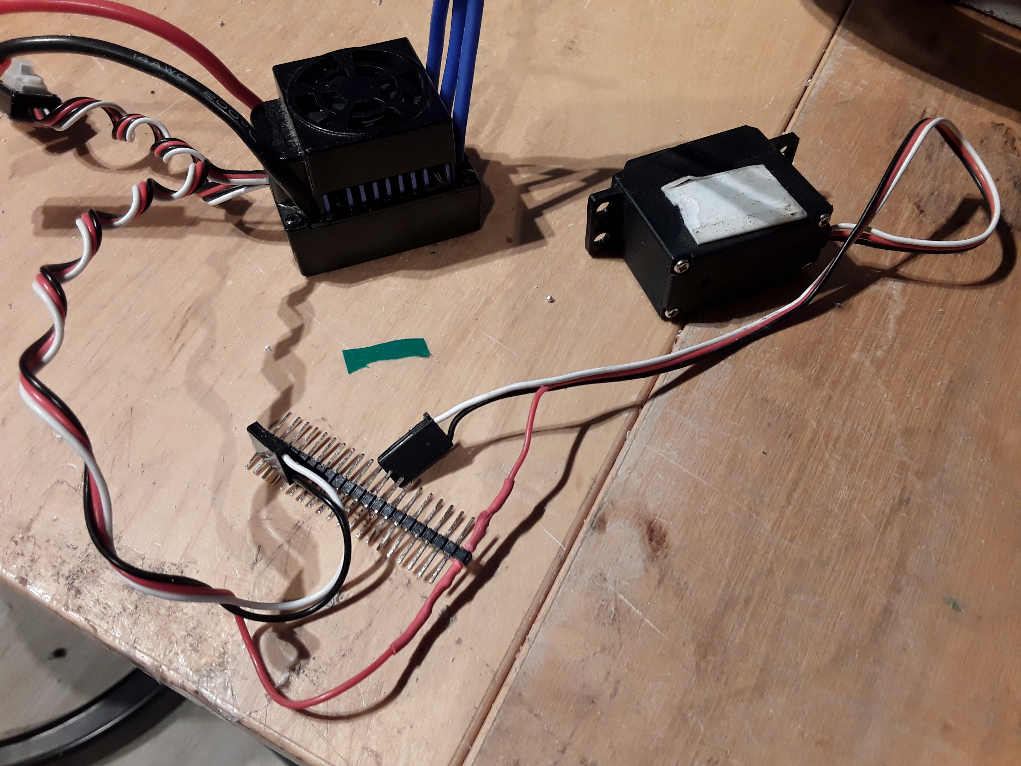
You mentioned “pull the red wire out of the ESC and servo connector and use a double pin to connect them together. A thin piece of solid wire or such might work too.” How does that look like eventually? Do you mean I then connect the double pin with the middle pin on Navio2? I do not fully understand what you mean by that. It would be great if you could put a photo of how do you connect them together.
Any recommendation you have for the sensored brushless motor/ESC combo? Accurate control and positioning in low-speed scenario (say 15-30) is very critical for my experiment, so I do want to take this into consideration at the first place.
The servo needs power, the ESC provides it and the Navio does not like 6V. So you pull out the red/middle wire out of both servo connectors. Simply lift the plastic tab with a sharp knife and pull the crimped connector out of the plastic housing. You then have two female connectors. To connect them together, you push a short piece of wire in one of them and plug the other one onto it. This way, the servo gets powered by the ESC and the Navio does not get fried by a too high voltage.
You only need one doublepin of course, I just had no single one lying around. Then just connect the servo connectors back to the Navio. (This is the original steering servo and ESC I replaced in my Trooper )
I bought the motor/ESC combo with the lowest kV rating. I think it was 1800kv. The difference is really remarkable. No stuttering or cocking anymore and it goes at snails pace. You will need the matching programming box. The ESC is setup for a racecar, not a rover/robot, so you have to disable all the boost and turbo options or set them to their lowest setting.
You can find the programming box under Accessories.
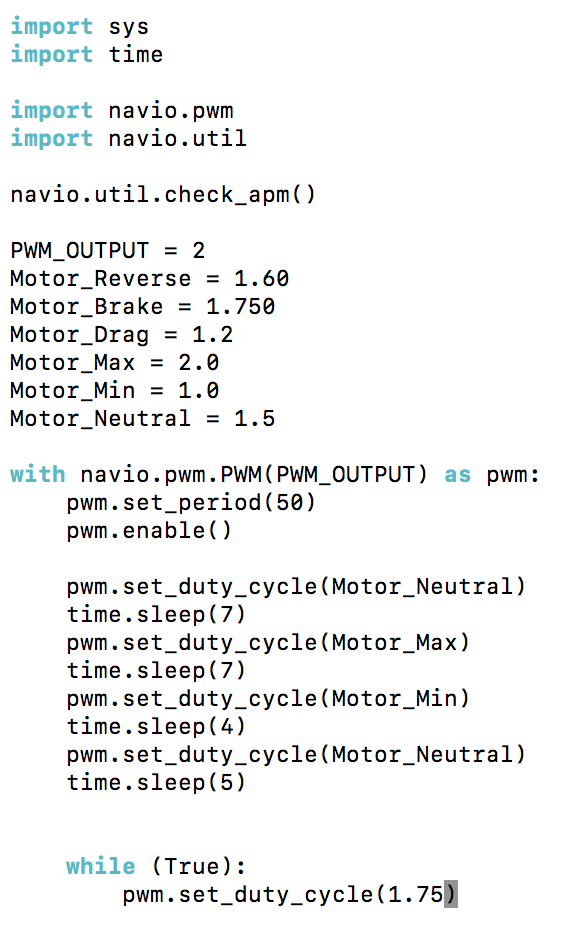
Yes, it turns out to be a issue with power supply/pin connection. But the motor still does not work. For the PWM code for controlling Motor, should I use different values to set the duty cycle of PMW to be able to increase/decrease the speed of the Motor? I am still do not quite understand why it has to be 1ms, 1.5ms and 2ms for the duty cycle…
Another question relevant to Servo/Motor control: I wonder if you have ever tried putting a wheel encoder for measuring the angle of rotation of the RC cars? I would like to do a vehicle localization based on Dead Reckoning and need the value from the wheel encoder. But I am a bit worried about the reliability of the motor control in low speed… How slow can that the motor you suggested moving. 20mph would be enough for my experiment.
You are working with RC hardware and the PWM range for RC is usually from 1000us to 2000us. 1500-1520us is neutral in most cases. Servos can sometimes have a greater range, but some may hit their mechanical limit and be damaged if you send a too high/low signal.
For what I understand about wheel odometry/dead reckoning it suffers from wheel slip. So you would have to use encoders on all wheels to notice when one wheel is turning faster than the others or/and use other sensors (GPS, IMU) to correct remaining errors. Putting sensors on the small wheels might not be easy. Perhaps you could use the motors sensors as an encoder, by tapping into the wire harness. For quadrature encoders there are two sensors 90°out of phase, but the motor has 3 sensors 60 or mostly 120edeg apart. Since you can not connect the encoder directly to the Navio, you would have to use an Arduino or similar with rosserial to read the sensors. There you could also convert the 3 sensor signal into a quadrature encoder signal or rpm with direction. But do not ask me about the code…
My Trooper could go really slow without any stuttering, with the motor I bought. 20mph are 8.88m/s in real units and this is fast for most robots/rovers. I would not expect that dead reckoning is working reliable at those speeds.
Thanks! I might have to ask for code of controlling the motor…
I made some progress by being able to calibrate the ESC correctly (The motor will sounds long/short beep pattern). But still the motor is not moving. Below is the code I used for calibration and control. It seems setting the duty cycle to 1.75 does not have any effect…


 and this is fast for most robots/rovers. I would not expect that dead reckoning is working reliable at those speeds.