Hi! I have a set of 2 3DR clone radios (air and ground modules) which I am trying to integrate with Reach and Reach RS, however I haven’t been able to get them talking to each other. I have tried different approaches but I cannot seem to make them work. I am pretty much a rookie using Reach so I would like your help to know what I am doing wrong, please!
Reachview version used: v2.9.0
These are the exact radios used: https://www.amazon.com/gp/product/B0196LF6PW/ref=ox_sc_act_title_1?smid=A2W7KWOTDOLSRV&psc=1
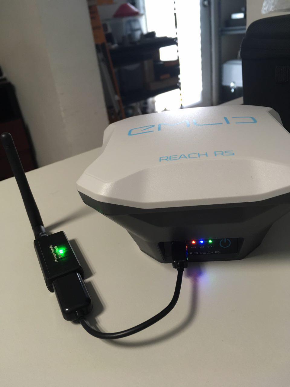
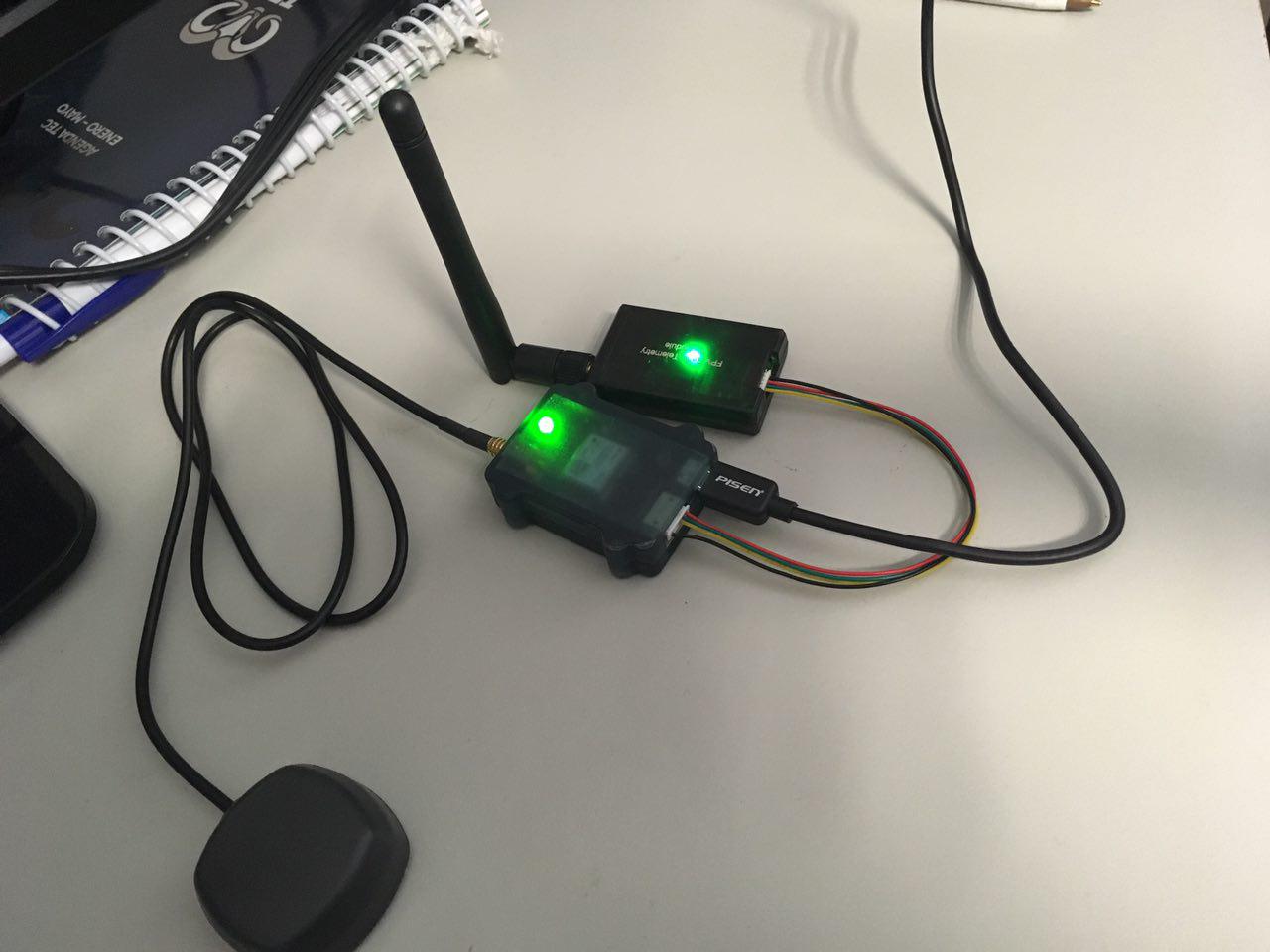
When I connect the radios, they seem to be working properly based on led behavior: they both flash a solid green light and there is a red blinking led indicating data transfer. However, I cannot make Reach and Reach RS connect to each other via radio. I had previously achieved successful connection of both devices using Wifi, but when using radio the gray bars just never show up.
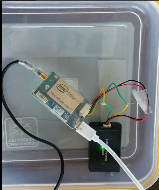
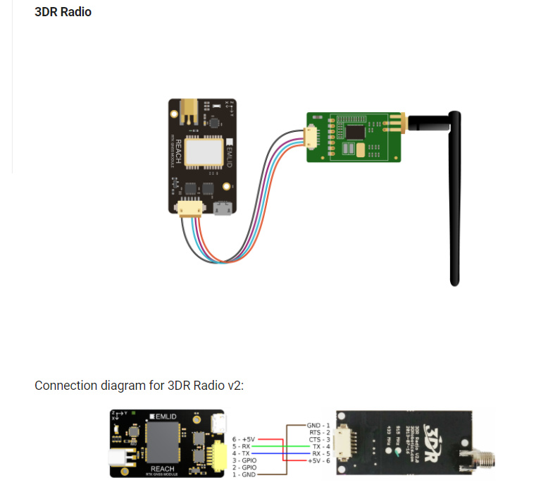
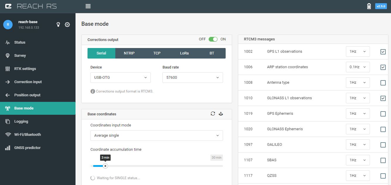
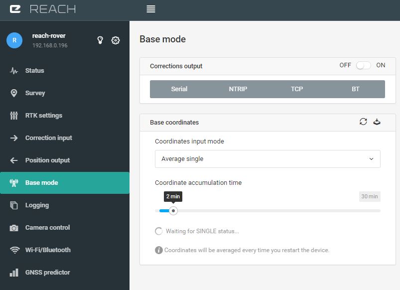
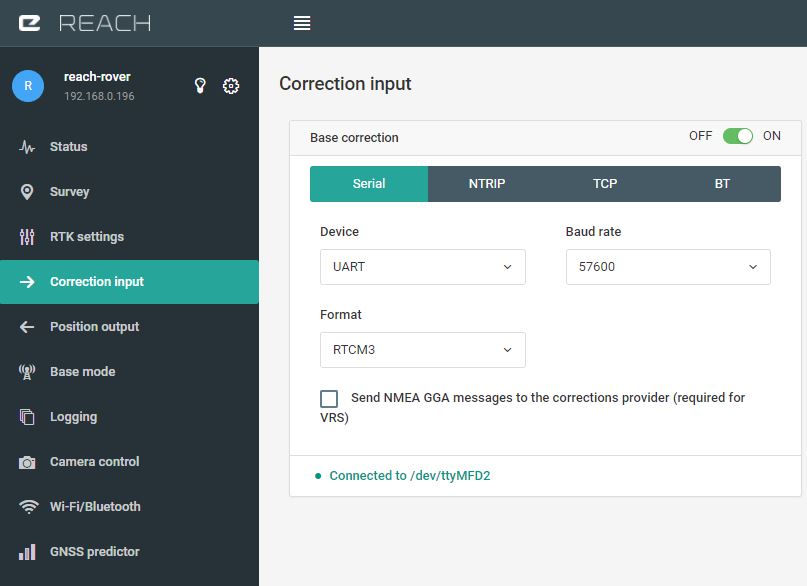
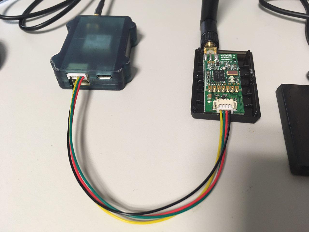
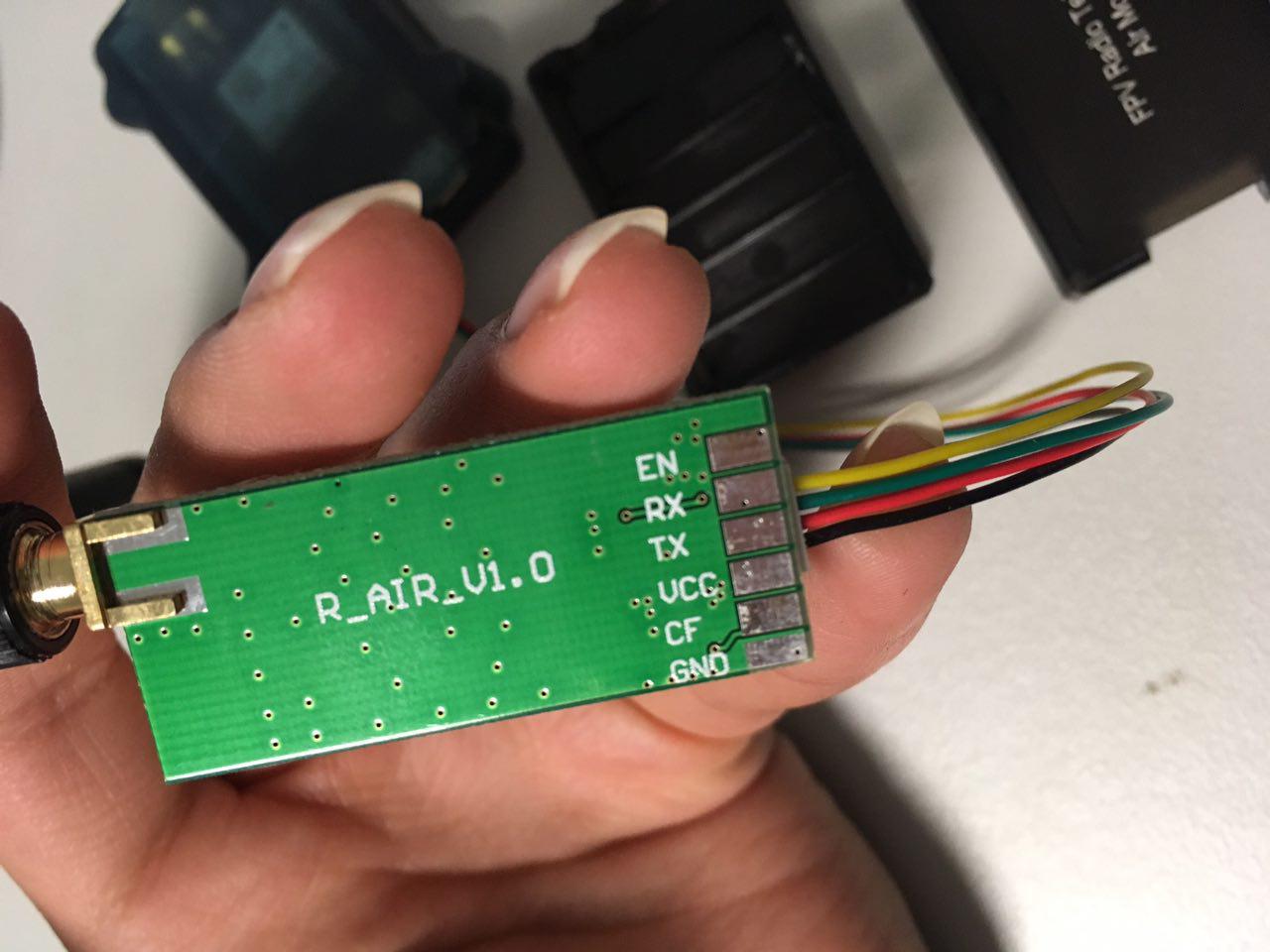
Reach RS is set as the base, connected to the ground module radio via USB-OTG, and Reach is set as the rover, connected to the air module radio UART via DF13 port, and powered using the micro usb cable connected to an external battery. I included some pictures to walk you through every step I’ve tried.
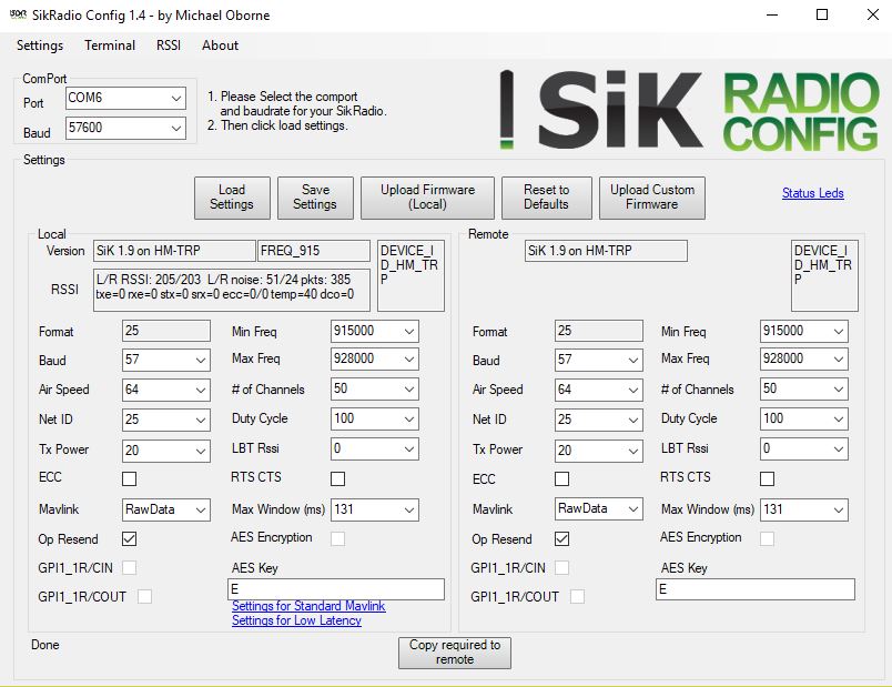
First I checked for radio communication using Sik Radio Config 1.4, everything works fine.

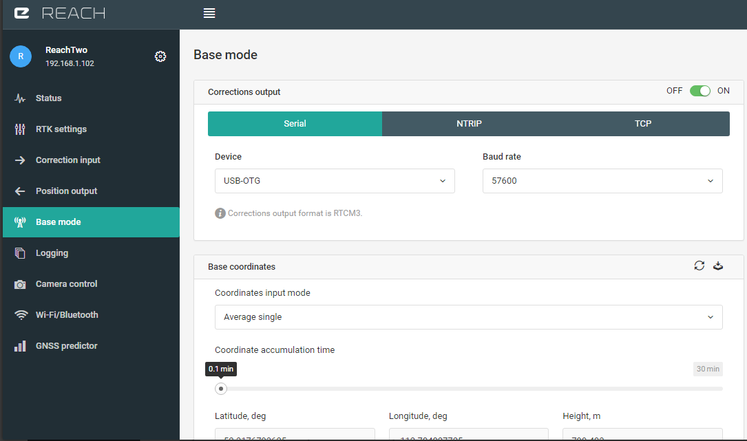
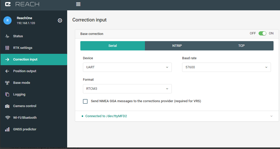
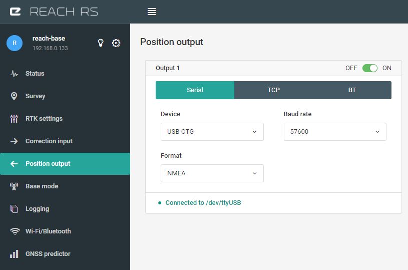
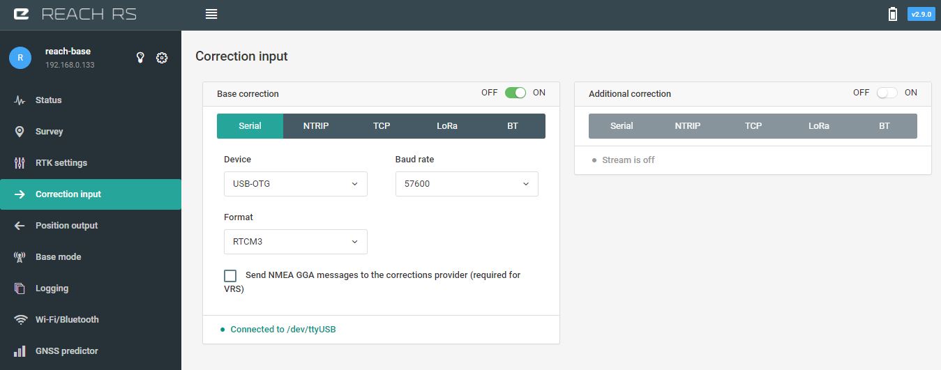
These are the settings used for Reach RS and Reach:

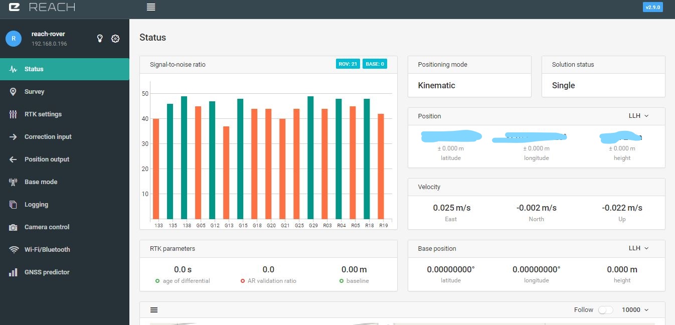
And these are the status bars of each device (no gray bars! ![]() ) :
) :

This is the physical setup of each device:
Any ideas on what might be wrong? Thank you very much!