


Just wanted to share some diagnostics and ask for some guidance with the WiringPi utility. Because I had to run some diagnostics to document the different GPIO configurations with Navio+, Raspberry Pi 2 and various operating systems… Because I’m building a driver for Windows IoT, which means it must be ACPI compliant, with PIN configurations set in the ACPI table. Besides making sure the hardware does not malfunction, it enables plug-and-play to map the hardware to your driver. So this is critical to get right!
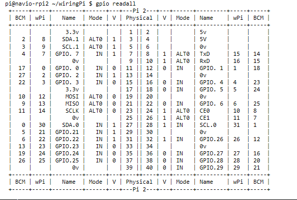
First of all let’s look at the standard GPIO configuration with Navio connected:
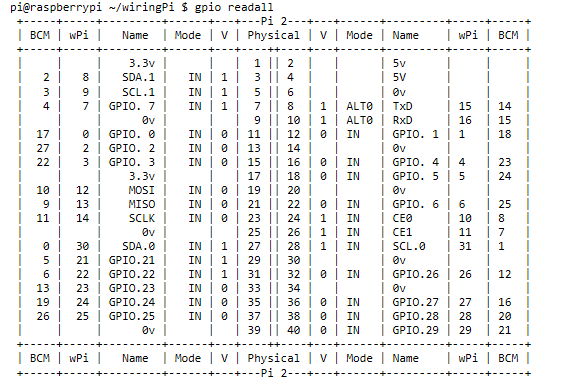
Then without Navio connected and a fresh install/firmware/drivers from the latest Raspbian “Jessie” build:
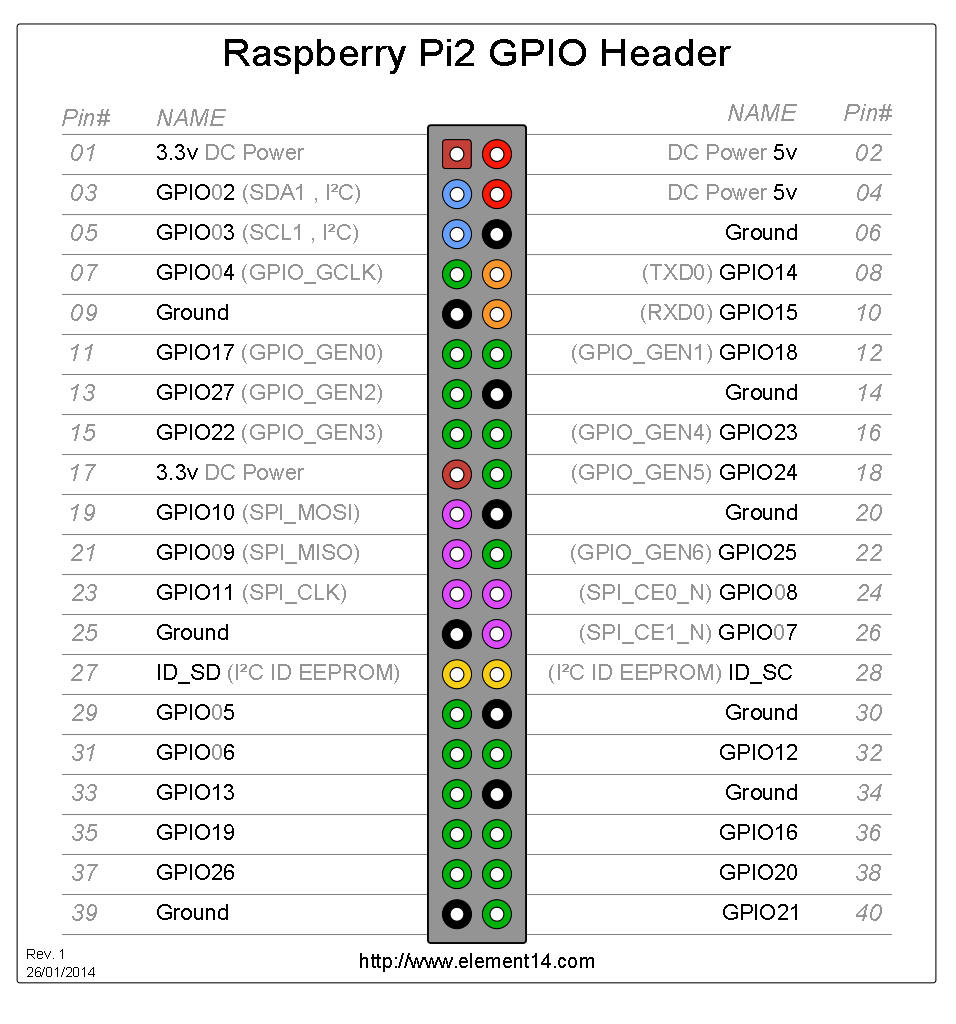
And finally from the Microsoft Windows IoT documentation (here: http://ms-iot.github.io/content/en-US/win10/samples/PinMappingsRPi2.htm):

By “defaults” I mean either output mode (no pull), or input mode with one of the “pull-up”, “pull-down” or “none/floating” resistor/circuit options.
I’m trying to correlate but it seems there are some points which are not clear, maybe somebody can help answer:
- In the WiringPi table does “V=1” mean “pull-up” and “V=0” mean pull-down?
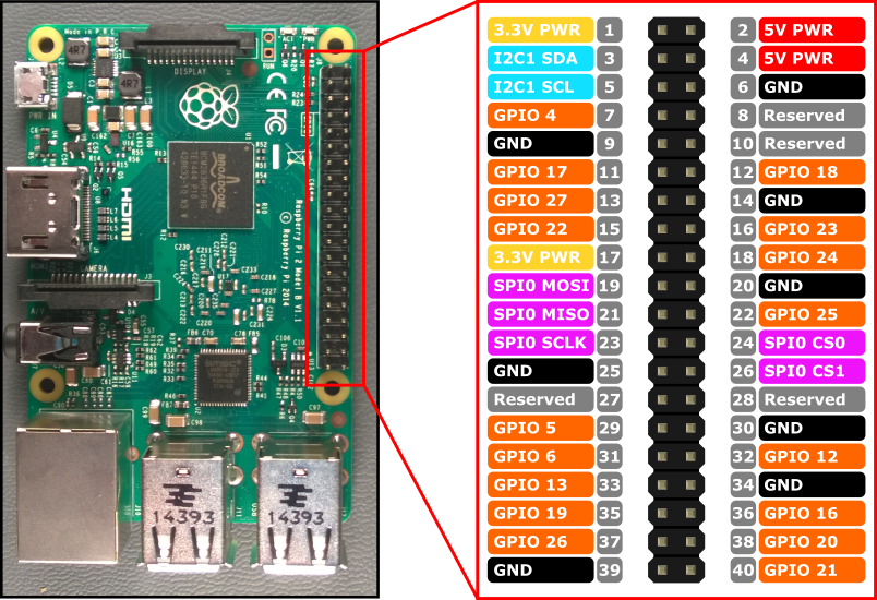
- Somehow WiringPi “physical” pin numbers are wrong. The Microsoft pin numbers do match the other sources, for example as documented at Element14 (http://www.element14.com/community/docs/DOC-73950/l/raspberry-pi-2-model-b-gpio-40-pin-block-pinout):
Does anyone else know WiringPi enough to tell me the answer to these questions? I know how to build the ACPI table in ASL language, but don’t want to boot my device with Navio connected and the opposite input pin/resistor configurations until I am 100% sure.
If nobody knows, the next stop would be the Wiring Pi blog of course. But I wanted to document the configuration with Navio here and see if anyone can see any points of caution before I start sending and receiving signals the wrong way around ![]()
