Getting sub-centimeter precision with Reach RS2 and EzSurv

Millimeter-precision, tsk, that’s not possible with GNSS! Well, it is actually!

The key is either multi-base and/or multi-observation and then combine these using a Least Squares Adjustment capable GNSS processor such as Effigis OnPoz EzSurv.

In this example I am using the clubhouse of a local modelflying-club, 6 GCP’s and 4 CP’s, spaced roughly 5-6 meters apart.
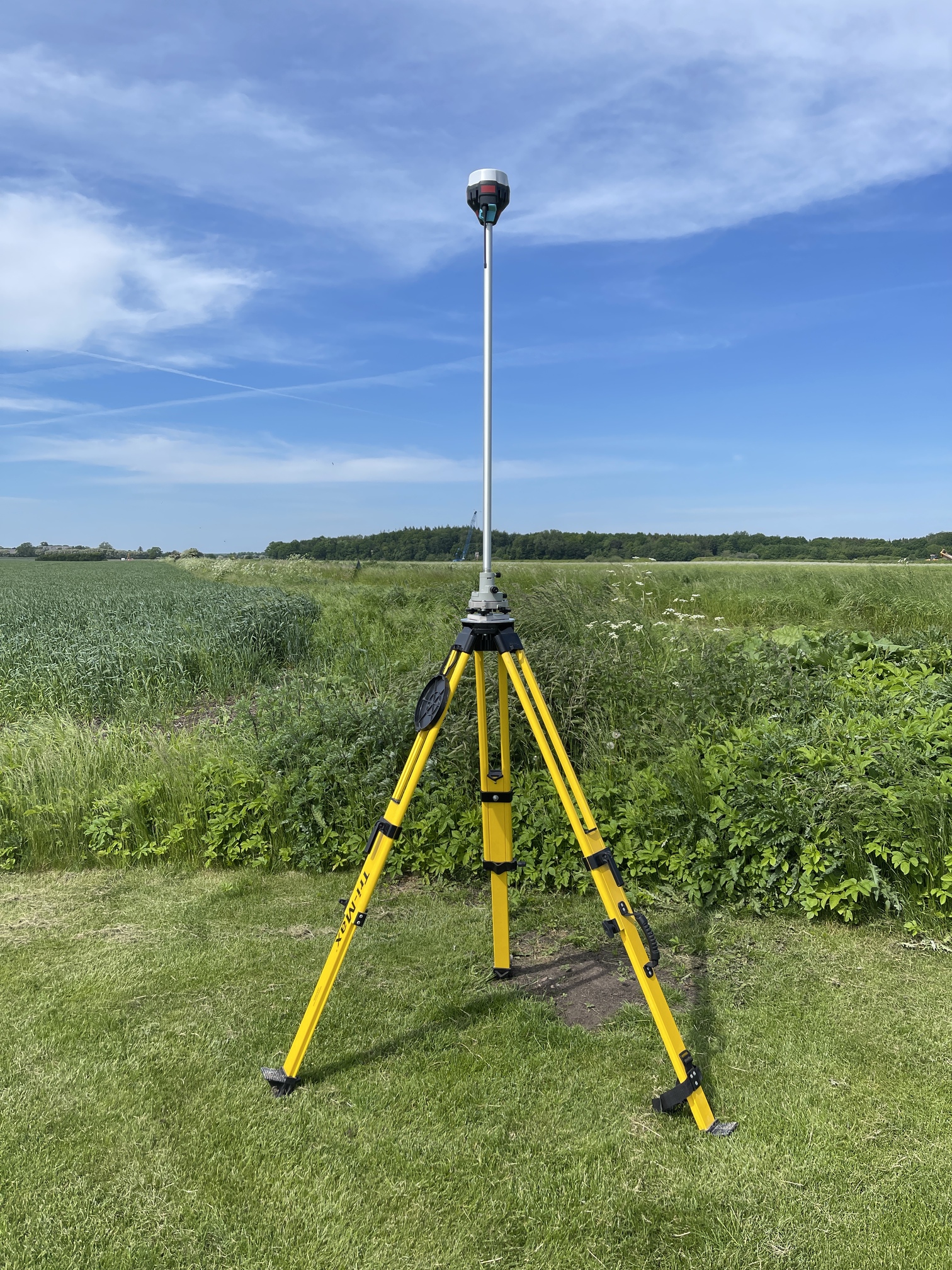
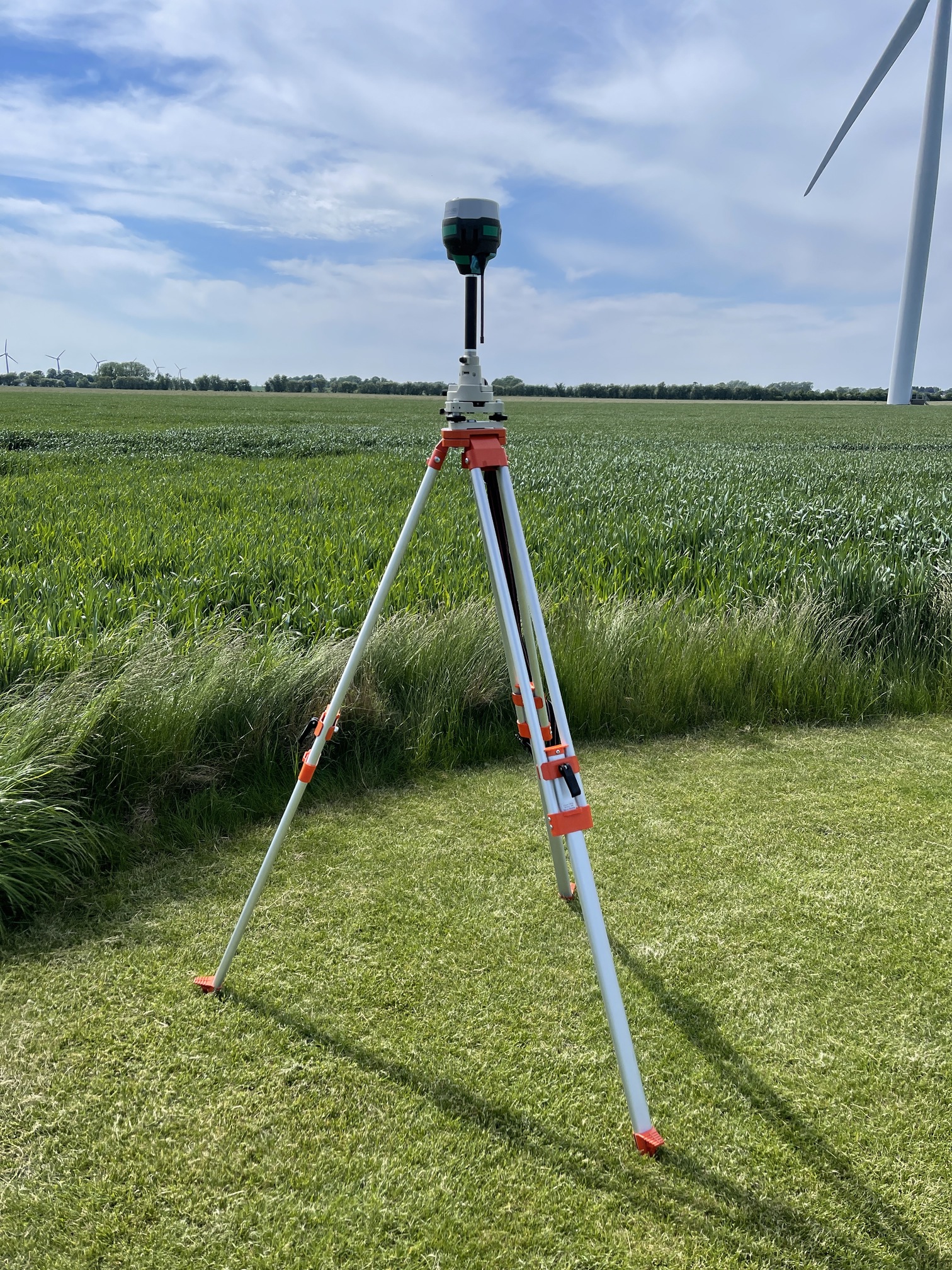
I am using 4 RS2’s in total, 3 as bases, 1 as Rover + an NTRIP connect to a national supplier using RS2’s (RTKconnect.dk). The NTRIP-service is used to determine the absolute location.
Resolution of material is around 0.003 m/px (24 mp shots, from DJI Phantom 4 Pro and APS-C sized sensor in a compact-camera, both pre-calibrated). Using around 500 images.

I will do 3 different combinations:

  • NTRIP + Rover, baseline 21 km, single observation per marker.
  • Single base + Rover, baseline <100 meter, 3 observations of 30 sec to 1 min observation-time per marker. Network-adjusted.
  • 3 Bases + 1 rover, baseline <100 meter, 3 observations of 30 sec to 1 min observation-time per marker, totaling 9 different solutions pr marker (3 bases*3observations). Network adjusted.

So let’s jump right into the results:

NTRIP + Rover:

Checkpoint total error: 0.047 m

Single base + Rover, 3 * obs pr marker:


Checkpoint total error: 0.0063 m

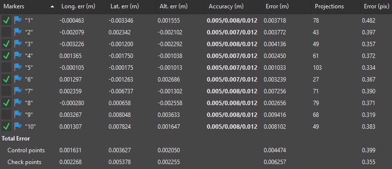
3 Bases + 3 observation pr point:


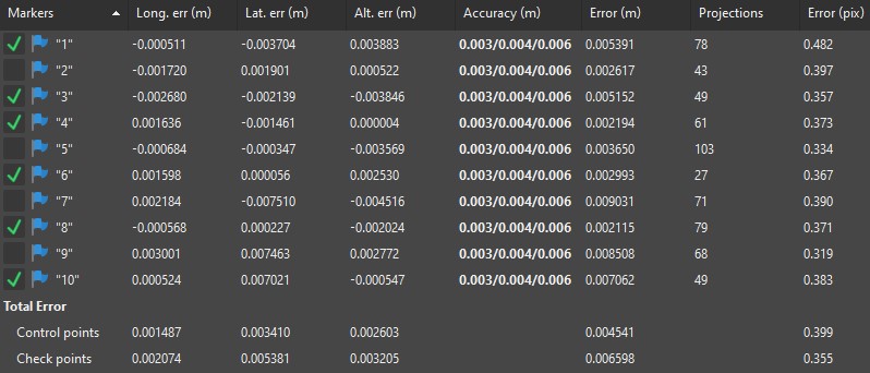
Checkpoint total error: 0.0067 m

So, the multi-obs per point seems to be where the magic really starts. However, if you also need accuracy, the 3 bases will help in solidifying the absolute accuracy.

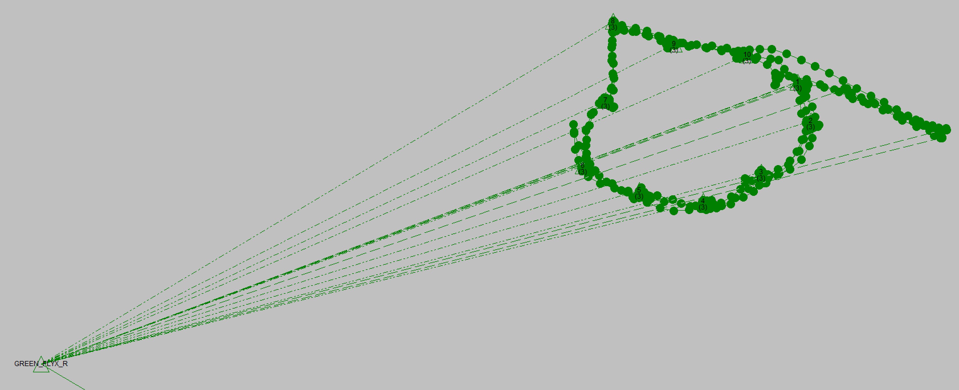
And then, finally, a small 3D model of the aforementioned clubhouse. Not perfect, but still pretty happy with the reconstruction of the smaller details:

19 Likes

Good reports.

Does the software allow entry of systematic observation error, i.e. setup errors for the bipods ?
No observation setup is perfect.

Usually I include these errors using StarNet. In any large network we do, all setups have error, such as the vertical component, i.e. being plumb and level bubbles are in good adjustment. For us using fixed 2 meter survey tripods equipment, usually the error component for good adjusted equipment is 1 cm (0.03’). We always calibrate our tripods before any small or large network. Doing networks for submittal to state or federal agencies always requires vertical measurement as well as slant heights of the receivers. Also all receivers are oriented to north . Temperature and barometric measurements are also required for each observation station.

Good work Christian !

3 Likes

Curious. I noticed Trimble software asks for this.

Always wondered why?

Thanks Bryan.

1 Like

Nice job Christian! Curious, is the camera used, the standard one supplied with the Phantom 4 Pro? Doesn’t sound like it at 24mp. And I take it that the 3 shot routine was taken one right after another while setup on each point?
Thanks, Mark

The slant/vertical measurement is basically a check on the tripod used. All high accuracy networks performed require a rod accuracy report per station along with temp/barometric measurement per station.

1 Like

Thanks !

It supports inputting a horizontal or vertical error component (intial + ppm) to verify vectors when network adjusting. On top of that you can input sigmas for the reference stations.

Can you tell a bit more on how the slant heights are calculated?

1 Like

Thanks !
Nop, that was an oversight for my part, it is indeed the standard camera, so 20 mp for that, and then 24 mp for the handheld camera.

The 3 obs’ are spaced 1 hour apart each, to make sure that satellite geometry has changed significantly, and thus the resulting position calculation is also different.
The further apart timewise the better. Also, the lifting, centering and levelling of the pole is slightly different from obs to obs.

2 Likes

You know the rod heights (vertical component) and you know the radius dist per the calibrated antenna variables, you can compute the true slant height component that you measured. Most manufacturers used to have a simple table to compute the slant height based on any vertical height. Measurement of the slant height is a check on the measured vertical height or vice versa.

Simple trigonometry. There are also formulas for the rod deflection based on adjustment routines.

1 Like

I’m assuming it’s a typo but 0.003cm per pixel?

Nop, no typo, GSD of 3 mm/px, probably less in some instances.
The images are a mix of aerial shots and handheld shots taken from the ground.

I think he meant that the units should have been meters per pixels, not centimeters as the way it’s written it’s 30 micrometres.

2 Likes

Ah yes! Thanks! That is indeed a typo.

Whoever cuts the clubhouse lawn needs a high five, that grass is looking healthy and lush.

Edit: I now see R2D2 cuts the lawn.

1 Like

Hmmm? Did R2D2 cut it that well? Or a traditional mower… and then R2D2 just maintains it from that point?

From what I understand, those automous mowers just maintain a little off the top all the time? (more frequency vs waiting a week or or so) Kind of like Roomba’s “maintain” light minimal vacuuming after a full fledged suction traditional vacuum first?

I think like most robots R2D2 is better at his job than most humans, but is not much for conversation. I wonder if he is smart enough to know if its too rainy, dew laden, or hot to cut?

This topic was automatically closed 100 days after the last reply. New replies are no longer allowed.