Are there any advantages to the harxon? It is listed at 370g, so probably heavier than I want.
Your home made mount looks pretty professional. What sort of connection joins the antenna to the top of your pvc mount?
The Harxon is a calibrated antenna with distances to the L1/L2 phase centers and are used for precise surveying. I’ve checked the helical antenna with known passive control marks (1+ hour static observation) and horizontally I’ve obtained 2-5cm accuracy, not so good vertically (usually 5cm or more). For your purposes, it would be lighter and cheaper. Accuracy would be sufficient for your purposes.
For the mount, I just went to a hardware store and got some 2"dia PVC pipe. I drilled the holes with a drill press to get the exact center for the bipod mount and antenna mount. I used end caps for the pipe for the mounts. There’s only two small screws to mount the antenna to the end cap, so I counter sanked the base of the antenna into the end cap about half the width of the cap (about 5mm). This gave a more stabled mount with the available two screws. For the bipod mount, I drilled a 5/8" hole with the drill press and used a female 5/8"x 11" survey adapter. I was pleased with this as it just came in my mind figuring a mount. You could do the same for your handle. In fact, you could just tape the mount to the handle or make some kind of quick connect/disconnect. The parts cost was less than $5 or about. I’ve been meaning to make a revised mount to include the LoRa radios but just hadn’t gotten around to it. There’s other mounts that are better than mine, one guy 3D printed a mount to include the M2, battery and LoRa radio/antenna in one unit. It’s pretty slick. Just search under M2 antenna mount.
Hi @markbneal,
Indeed, you can use Reach M2 with a multi-band GNSS antenna for your survey. However, here are some things you should know before making a final decision:
-
You should provide proper ventilation to prevent overheating of Reach M2. It can be hard to provide it in a backpack
-
If you’re going to work in rainy weather, you need to think about how to protect Reach M2. It doesn’t have protection from water and dust
When you get a Fix solution, we usually recommend 40 secs to collect a point.
Also, I checked that the NTRIP station that you want to use transmits corrections in RTCM3 and NZGD2000. So, I think it should work fine. This guide about coordinate systems in New Zealand will help you set your rover for a survey with this NTRIP base.
It’s possible to output the position for both Android and iOS via TCP connection. However, for Android devices, you can also configure the transmission of coordinates via Bluetooth.
We’ve never seen the use of our receiver with a platemeter before. So, I’d be curious to see how your research will go!
Thanks for the feedback. I’ve ordered my gear and will look into the cooling and moisture/dust protection options.
For the Android device (i.e phone), is there a minimum OS version (or other specs) that I should consider?
Hi @markbneal,
ReachView 3 can work with Android 5.1 and up. Other than that, there are no special requirements.
Posting an update on progress.
My Reach M2 has arrived, and now in a functional prototype!
Platemeter
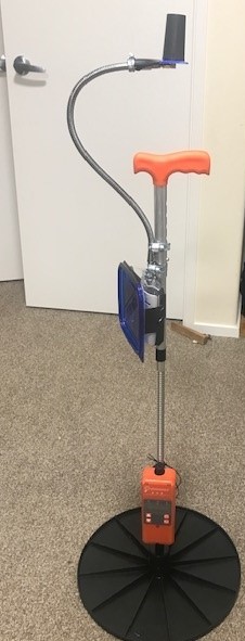
I have mounted to a Platemeters G1000 platemeter (Described here, available in NZ from Farmsource here. Alternatively, the Trutest EC20 here has similar capabilities. Probably the main consideration is third party software integration, which differs by device.
Accuracy
Without corrections, reported accuracy for latitude and longitude are sub-meter. I am now getting corrections via LINZ Positionz service described here - Thank you LINZ! Note, after signup, service is available after 6pm next business day. That brings latitude and longitude accuracy to 5cm, more than sufficient for our purposes!
Mounting
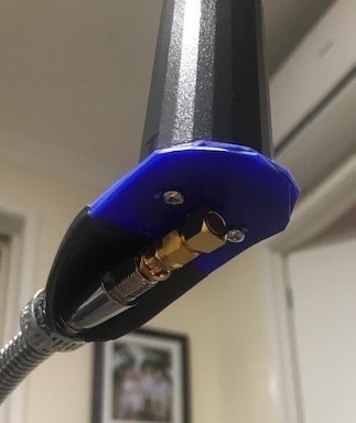
I have a first version prototype mounted as per pictures. Regarding the design choice of a semi-flexible mount for the antenna, farms (even research farms) are a place where things will get knocked around, and if the antenna is knocked for any reason, I’d rather it moves out of the way then crack (@$USD200 a pop). The flexible lead was donated by one of my children via their desk lamp, available here - Thanks Brian for the suggestion! While a flexible lead reduces reproducibility for height data, the height data is not super important, as our friends at LINZ are pulling together LIDAR data for all of NZ - thanks again LINZ!
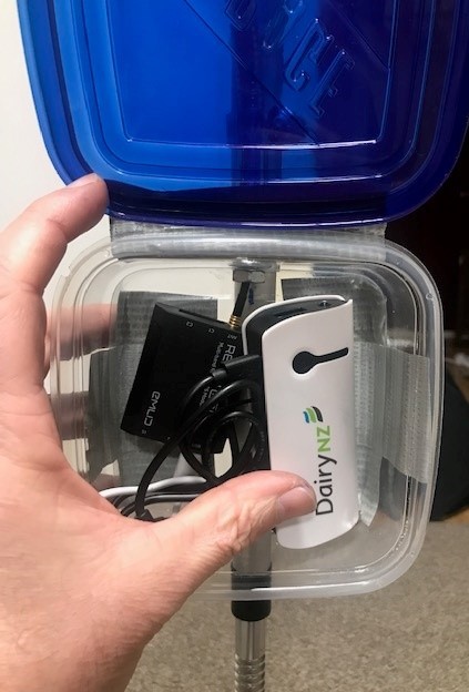
Once I had it in my hand, the small size and low-ish power draw meant mounting everything on the platemeter was a good option over what i’d originally envisaged in a backpack. A range of parts came (or are on their way), and I’m still looking for the final enclosure for the USB powerbank and reach device. 10mm M2.5 bolts are used for the antenna mount (be careful not to go to deep in the antenna), with an elbow, some plastic, tape and a hose clamp - I may add some silicone for waterproofing.
Power
The USB powerbank is 5Ah from memory, peak output 1A. I understand the draw to be average 200mA, so that should be plenty of juice, though the specs also list max draw of 3A here, so perhaps testing may show if this creates some some problems?
Data Collection
The platemeter app is available on iPhone and android, but an android is required for the phone gps data to be replaced with the rtk location data. The model I will be trying hasn’t arrived yet, but is a Samsung XCover 5. This was chosen for IP68 water tightness and apparently ability to use while wearing gloves. Purchased from Spark.
the XCover 5 combines IP68 watertightness and dust resistance with the convenience of a replaceable battery. Increased touch sensitivity lets you use the immersive 5.3” HD+ display while wearing gloves or with damp hands.
Cost
Platemeter ~$NZD1,150
Reach M2 kit ~$NZD1,000
XCover Phone ~$500
Powerbank, mounting pieces & enclosure ~$250?
Total cost ~$3,000
Pictures
I like your design Mark ! Especially the flexible mount for the antenna. Pretty smart design !
Hi @markbneal,
Wow, you really did a great job! Nice that you shared this with us!
Have you already managed to test this device in the field?
I’ve finished my second stage prototype to waterproofing level that will hopefully stand up to a couple of months of field testing.
Design choices are largely to have this plug and play in remote locations if one component craps out or needs to be replaced (e.g. usb powerbank). That also explains oversized enclosure (most powerbanks are larger in a flatter form factor), and minimum of soldering.
Some pictures
Here you see a waterproof charging port (for the powerbank) installed into the left side of the enclosure. The cable on the port is quite stiff, USB C on both ends, and so I needed an adaptor to USB A to match up with the cord for the powerbank (I learnt a lot about USB connectors!). Installed on the right side of the enclosure, you see the on off button.
The enclosure is mounted to the platemeter courtesy of the flexible shaft which has a thread and nut at the top of the enclosure, and a bolt that goes through the back of the enclosure in the middle (nut on the inside visible in the picture).
This second picture shows the shim between the flexible cord and the hose clamps for alignment (paddle pop sticks!). Also you see the mounting through the top, and the bolt goes through the lowest hose clamp.
What might not be obvious is that the lower clamp is mounted at the lowest point to still be on the top part of the platemeter, which is height adjustable, so as not to interfere with the height adjustment. That also explains why the enclosure is mounted in landscape rather than portrait, so as to not interfere with the highest possible measurement of the device when the height adjustment for the handle is in the lowest position.
Here you have all the items stuffed in the enclosure. You may well imagine doing this a bit more neatly, though they may wait for the next version. The powerbank is mounted on double sided tape. The other pieces seem like they might be ok as is, with cords for packing! The external power button is wired into an inline button (usb connectors each end) that I bought to as to have easy access to neat solder pads and pre-wired connectors (I’ve mentioned before that my soldering is not awesome!)
And here we have the enclosure, and devices switched on. You see the status lights for the usb powerbank, and the the Emlid Reach M2. Note the reach leds are brightest when the device is mounted closer to flat, than on its edge. I also hit the places that weren’t naturally waterproof (particularly top hole) with silicon after I took these pics.
Parts
Some of the pieces I used, not quite a full bill of materials since I used some on hand cables/bits and pieces:
Hoseclamps
Elbow for antenna mount
Bolts for antenna mount
Flexible lead for mounting antenna:
Waterproof charging port (due to length and cable stiffness, you might want to change this)
Charging port cap
Waterproof on off switch (requires soldering)
The enclosure I used (You may find a more suitable one with a final list of components and easy access to cables and connectors under non-lockdown conditions to minimise size and weight)
USB cable with inline power switch
An adapter I bought to make all the other cables I had fit together!
Hi @markbneal,
That’s cool! I like to read more about your setup and how everything works. I’d just want to note that your Reach M2 is in a sealed container and can overheat. You may need to organize an additional ventilation system.
UPD. Fixed the typos
I’m hoping there is enough air volume for the heat dissipation to be fine. Otherwise I’d have to strip off the shell to connect to a heat sink? Do we have any reporting available for the temperature (from the Reach device), or any automated shutdown for when temperature gets beyond desired operating range?
Hi @markbneal,
Operating temperature for Reach M2 from -20 to +65 ºC. It may indeed shut down automatically if it overheats. However, we don’t recommend stripping off the shell 🙂. I can suggest a few other options:
- For example, make some holes in the container for ventilation
- Place your external battery and receiver away from each other. The battery can heat itself and heat Reach M2
However, we can’t be completely sure that the receiver will overheat because it depends on the conditions. In this case, you can do some local tests and check how your Reach M2 will work.
I’m going to assume for now it won’t be a problem - we’ll see what happens!
I’m not keen to make holes that would compromise watertightness. However, I do note an option listed under vented enclosures here that has a vent plug that looks like it allows air to escape - would this be of value?
Hi @markbneal,
I can hardly tell you if this device can help. In any case, I should warn you that overheating can negatively affect Reach’s operation. That’s why if you do any tests, you should do them carefully. I’ll be glad if it all works out!
Some questions with the data I should expect to get back:
The Lefebure NTRIP app appears not to be storing the log, or at least I can’t find it. The screenshot suggests some problems with permissions?
I think there is a log stored on the Reach device, which I will try and get off.
(https://docs.emlid.com/reachrs/reach-panel/logging/)
Another question I have is whether an android device can get data associated with the location data (e.g. estimated accuracy of a fix). It seems a sensible thing to have available, but the specific platemeter app does not record any location “metadata”. I’m curious if this is an easy fix for an app developer.
The platemeter app records the data in an sqlite database, which you can explore from R very easily. Reports can be mailed from the app in various forms, but only one of which currently has individual location data (in kml). Ideally I’ll come up with a plan to sync the sql database to a more permanent storage. Ideally I would be able to get Lefebure log and reach log in a similar way?
Some results from testing:
Here’s the data from my testing of the RTK GPS (Emlid Reach M2) with a platemeter app to record measurements using the mock location from Lefebure NTRIP app.
Top left was me repeatedly measuring near three posts (which were in a line) sequentially, repeated three times. There was one point off to the lower left, which was clearly out of spec.
Then I switched to four posts, in a 5m by 5m square, each measured, then repeated to get 5 readings at each post. Top right was a fail – not sure why. Two final tests (lower plots, separate days), appear to work, though bottom right has one measure that looks out of spec.
I will check logs for location apps if I am able.
Plot using R and ggplot after reading platemeter data from its sqlite database. I’ll make a public GitHub repo of this if there is demand.
The test site:
Hi @markbneal,
It’s hard to say exactly what the cause of this may be. I haven’t encountered this error in Lefebure before. If it disturbs your work, let’s try to figure it out. Did you try to record some logs in Lefebure, or did these error messages appear for no reason? If the last, does Lefebure stop passing data to the platemeter app?
Also, you’re right that you can record raw data logs via ReachView 3. However, I’m not sure if Lefebure can record it.
Yes, Reach M2 streams its position in NMEA format, including coordinates, estimated accuracy, etc. However, I assume Lefebure doesn’t pass this data further, or the platemeter app can’t receive or read this data. I can’t say if it’s an easy fix for devs or not, but it should be possible since Reach sends this data. I’d start with checking what data comes to the platemeter’s app from Lefebure.
I’ve sent to field with another person to run, so unable to test direct it myself now. We’ve had some disconnections, and so they are upgrading the power bank to something that is rated for 3 amp output (the test powerbank was only rated for 1 amp) to see if that fixes it.
On the Lefebure NTRIP app failing to store the logs, I asked Lance (creator of the app). His reply notes it is a known issue with Android 11, and he hopes to fix it in the next month or so. For a short term fix, try Android 10 phone.
Hi @markbneal,
Thanks for keeping us posted on your progress! That’s interesting information about Lefebure.
Yes, about this:
To work with Reach M2, you need to use the 4.75 - 5.5V power sources with up to 3A. So you’re right. This should really help.