Emlid Flow 12.2 release includes several enhancements to speed up and make your fieldwork more flexible.
Traverse tool: calculate an inaccessible point from 2 points
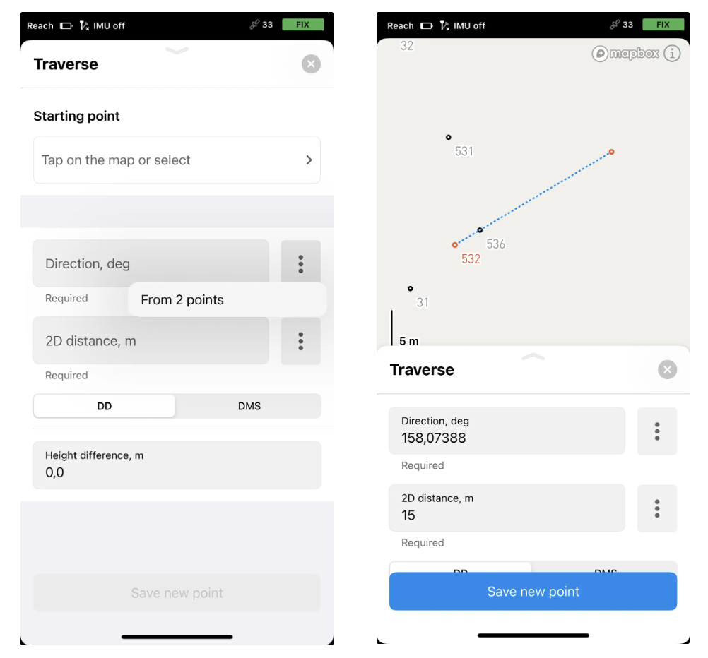
The new From 2 points option in the Traverse tool included in the Survey plan allows you to calculate an inaccessible point—or update a designed one in the field—using just two auxiliary points aligned with the target point and a measured distance to it. Emlid Flow then will compute the coordinates for you—no need for a compass or protractor to determine the direction. Do as follows:
Define the line from the target point.
Collect two auxiliary points on the line.
Using the Traverse tool, specify the starting point and calculate the direction based on the auxiliary points.
Specify the distance from the closest point to the target point.
Here it is! Don’t forget to save the obtained point.
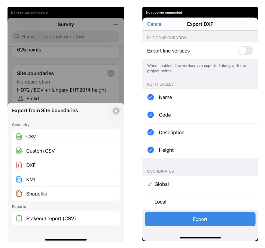
Updated export settings
Emlid Flow and Emlid Flow 360 now use consistent export settings. Both apps group formats by type and make it easier to configure exports through a more streamlined interface.
Additional coordinate systems have been introduced for Jamaica, Norway, Costa Rica, and the Netherlands, along with the new ‘JPGEO2024’ geoid for Japan.
Make sure your app is up to date to access the latest features!
While using this method to traverse to a target point is good for tying-in trees, it is not sufficient for tying-in property corners and other items of high precision without the aid of a precise optical instrument to make sure the angle point is on the line between the distance point and target. Is there a distance-distance method in Flow to calculate an unreachable target point, where the surveyor ties-in one side of a triangle with control points then completes the remaining sides with a tape measure from each to the target point?
Thanks for bringing this up! To ensure we’re on the same page, you’re referring to creating points at a Distance/Distance intersection, like this command, right? That’s a great feature, and we’ve also been thinking about it. Intersection tools are already on our roadmap, though I can’t promise any ETA yet. I’ll keep you posted if there is any news.
Yes. And here are others that might be helpful. It is also helpful to be able to dictate line or direction by either dictating or inverse between points.
I will admit ignorance on the Flow capabilities in this regard, but the typical method I use to measure a property monument hidden under a fence line is the following:
-insert 3 spikes in the ground ideally fanning out from the point at around 45 degrees and less than 1’ away
-measure the 3 spikes with the GNSS (measure them with multiple shots, different times of the day, etc. to meet the project’s specified precision)
-tape from each of the spikes to the monuments and note the distances
-tape from each of the spikes to the other spikes and note the distances
I typically place the measurements in the codes of the spikes. One then has at least two options:
Draw circles of the measurements from each of the spikes to the monument. Draw a line from the intersection of two of the circles and snap it perpendicular to the third circle. Place a point at the mid of that line. Generally, I find that the drawn line has a distance of 5 to 10mm. This method can be done in the field with the DC software I use. The taped to the other spikes act as checks.
Take all the measurements back to the office. Plug them into Starnet (or your equivalent) and enter in the taped measurements as 2D. Ideally, the spikes were all roughly level and the measurements were done level. Create a point at the rough coordinates of the intersection and apply a weighting to it. One can then see the error ellipses and adjust as needed.
If Flow has the ability to draw rudimentary CAD items, one can do a lot of COGO. I will admit ignorance on that matter.
Either way, this new method works well for measuring trees.