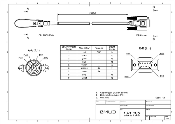
Hello, I bought the Emlid Reach Cable with a male DB9 connect but realized that I can’t use DB9 to power my Reach RS+. Does anyone know if the internal wiring of the DB9 cable is the same as the internal wiring of the non-DB9 cable so that if I cut off the DB9 end of the cable, will I have access to the wires which would allow me to power the Reach RS+? I’ve been looking at the wiring diagrams for both the DB9 connect and the non-DB9 connect (linked to this post) and it seems like if I cut open the DB9 cable I should have access to the wires that would allow me to power the reach RS+. Am I correct in this assumption or is there no internal wiring for the pins that are labeled as ‘np’ in the circuit diagram? Thanks!
A good question I’ve wondered about myself as backup option for a damaged cable.
I can tell you looking at both versions here that the cable itself is the same, identical markings and external dimension so all the cores will be in there.
The real question is if they are actually terminated at the Lemo connector end, and it’s not easy to check as both connectors are molded.
You could either become the sacrificial guinea pig and conduct a scientific beheading of the DB9 to satisfy our curiosity…or wait for Emlid to confirm the manufacturing detail…and if needed exchange it.
Using a meter I tested the Male DB9 cable, and it is as reported on Emlid’s diagram, that only pairs of pins 1-5, 6-2, 7-3 are connected. Just as Wombo stated, both the cables are of the same diameter, and I believe they must contain all the of the 9 wires in the DB9 versions. The same as the CBL 101 version with one end terminating in bare wires. They are just not connected as stated in the diagram 'nc".
Hi Todd,
Welcome to the forum!
We suggest using CBL101 to charge the Reach devices. We haven’t tested cutting the CBL102/103 to power up Reach, and there are different regulations for CBL101 and CLB102/CBL103. So, I can hardly confirm that such a modification will work.
Well, I cut open the cable and tested it due to Emlid not having a return policy for this sort of thing. It turns out that the internal wiring does not connect through to anything but pins 1, 6, and 7 which means that I cannot power the RTK unit using the cable that I currently have and will need to buy a different cable.
Hi,
unfortunately I have also bought the wrong cable for powering the RS2+ via the DB9-CBL. Maybe you (EMLID) could be a little more specific on the documentation site, which cable to use for powering the device? Or have I overlooked something?
I thought I could buy a simple solution without having to solder ![]()
Currently I’m using the usb-c port to power the RS2+, but it’s outside on the roof in all weather and I’m guessing the usb-c isn’t made for staying outdoors in the rain? Or is it? That would be great news!
Thanks for a quick clarification!
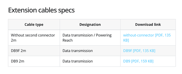
CBL101 is for connecting power. The other DB9 cables are for connecting to data collectors etc which ONLY transfer data, no power. The DOCS have pinout diagrams for each.
Hi Vincent,
Reach cable without connector is for powering Reach. I’ve passed your feedback regarding adding more information to our documentationn; we will discuss it.
We usually recommend Reach cable because it’s easier to set up on the roof, and you can turn Reach on/off using the cable. It all depends on your setup and how heavy the rain is, but I don’t see a big difference between powering it via USB-C or Reach cable. Reach devices have IP67, but I advise you to make sure that the rain doesn’t trickle down to your power source using the cable.
Hi Olesia,
for the experienced, industry norms and the pinout details in the drawing are very clear - with one exception below. However, you do have to hunt around to find if the drawings exist to double check as there aren’t otherwise any clues to the actual functionality in the product name in the store.
I think the feedback here is valid, and considering Elmids target market it would be a good idea to make this clear up front. Suggest simply add to or change the product labeling in the stores for 102 & 103 to include something like “Data only, no power” or at least “Data only cable”.
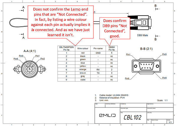
In addition, the primary issue raised in this thread does indeed highlight one detail inconsistency in the drawings that should be fixed. I had wondered about the internal Lemo pin connections myself; the drawings do indicate those pins are connected but it’s not easily checked and as we have found out they are not. This should be corrected in the drawings, detail here:
Hi Olesia,
Thanks for forwarding that info!
The thing is, except from the EMLID store, I haven’t seen any other webstore that even links the data sheet (like in my case), so there is absolutely no hint for the missing connections.
I’m sure there are many electronics people for whom it is entirely logical to first go to to the manufacturers documentation and search for the manual, but us laypeople simply want to buy the power cable and plug it in ![]()
Maybe you could simply hand out a JPEG version of the data sheets with those pretty images of the cable, so suppliers can use then alongside in their webshops.
Also, I like Wombos suggestion! ![]()
Again, THANKS for considering this!
Wombo and Vincent,
Thank you for the feedback and for taking the time to prepare suggestions; they are helpful! I’ll pass them on to our team, and we will discuss them.
Hi y’all, one more thing:
after connecting the cables correctly and double-checking 5x, I still couldn’t get my setup working – until I found this thread:
Initially I’ve had my cable hooked up to a USB-C power supply, but it wouldn’t charge, even though 5.0V definitively arrived at the purple wire of the EMLID no-plug-cable. After reading the thread above, I tried a 12V power supply, and now it works flawlessly.
So the 5V stated the data sheet (yes, 5-40V…) might work if the cable is only 0.1m long (?), or it means “floor-rounded 5V from actual 5.4V” ![]()
![]()
![]()
So my suggestion to anyone struggling & reading this is simply go for a stronger power supply. Works for me. ![]()
Maybe this is just due to my inexperience, but I assumed nc stood for “normally closed” rather than “not connected”, is this syntax common in other wiring diagrams? The confusion for me is that if it’s normally closed that would mean that there is a connection through the pin to the wire.
Yes, NC is standard notation for Not Connected in cable connectors & IC pins etc.
NC for Normally Closed is also valid but relates to switching devices such as relays and manual switches with no power or manual force applied.
Hi everyone,
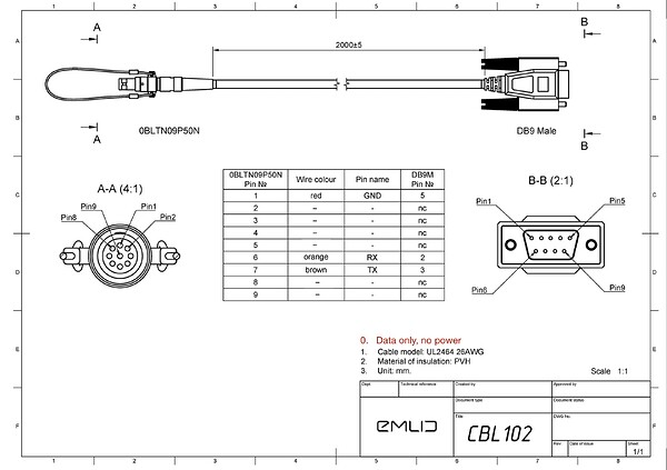
I also wanted to let you know that we have updated the information in our documentation and in our store to represent what each cable is for:
Thank you, everyone, for your ideas and feedback!
This topic was automatically closed 100 days after the last reply. New replies are no longer allowed.


