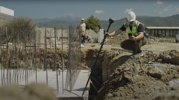
We continue delivering a series of posts dedicated to Emlid Flow in action. Today we’re showcasing how Emlid Flow makes site layout workflows more efficient. Transferring a design to a physical site requires precise measurements to ensure that structures, utilities, and infrastructure are positioned exactly where they need to be. This is where Emlid Flow and Reach receivers come into play.
Making the most out of input data
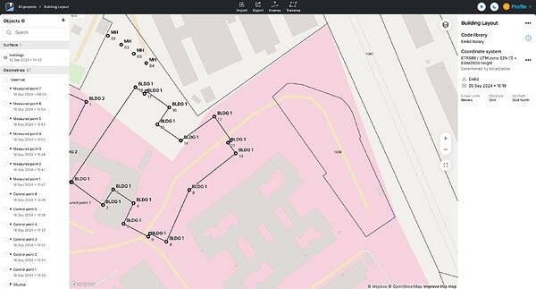
The key step is to gather and integrate existing survey data. With an Emlid Flow account, you can easily import CAD projects into the cloud-based Emlid Flow 360 app, set up or create a custom coordinate system, work with survey codes, and review your data from the comfort of your office. Once everything is set, you can carry on in Emlid Flow.
Collecting and marking objects
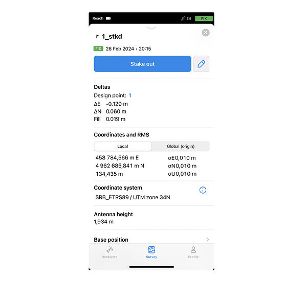
In the field, using Emlid Flow, you can stake out all imported objects—whether they’re points, lines, or polygons—and generate stakeout reports with deltas to ensure accuracy.
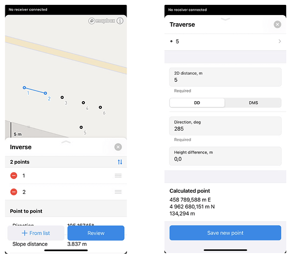
You can also use the Inverse and Traverse tools to calculate coordinate geometry for known points and create new ones. These tools are essential for planning engineering works and tracking construction progress on-site, reducing the need for re-surveys or office recalculations.
Exporting data for post-processing
After completing the layout, you can return to the office and easily export the stakeout report with deltas from Emlid Flow 360—there’s no need to do it in the field or transfer files between devices.
Whether you’re laying out a construction site or managing infrastructure projects, Emlid Flow and Reach receivers simplify the process of transferring designs to the field with high precision.
Have you tried using Emlid Flow for site layout? We’d love to hear about your experience in the comments below, or reach out to our support team at support@emlid.com if you need assistance!


