Construction project. Initially calibrated using surveyed control points and Trimble base and GNSS receiver (SPS986). Yesterday, I set up my Emlid Reach RS2+ as a base over an unknown point, logged into my state’s RTN network for corrections, set up a project, and measured a point for 60 minutes. Then, I set up my Trimble equipment over the same point and recorded a ground control point for 5 min and recorded the results in my data collector. Here are the differences in lat/long/ellipsoidal height as well as N, E, Z for each observed point.
Northing: 502077.634
Easting: 1404793.136
Elevation: 631.147
Next, I post processed the observed point in Emlid Studio using a the static processing option, entering a CORS observation and navigation file. This resulted in an ellipsoidal height of 530.795 and elevation of 630.97.
Can anyone with experience explain the elevation differences? Alternatively, which should be relied upon for use in RTK drone flights?
Side note, I have not yet run an OPUS solution as it has not yet been 24 hours.
First off your latitude and longitudes are different because trimble is in degrees minutes seconds (DD MM SS.sss) and the reach is in decimal degrees (DD.dddd).
But that has nothing to do with your question.
I do not know why the trimble and reach ellipsoidal heights are different.
I plugged your lat/long into NOAA’s Geoid 18 calculator and got a geoid separation (“N”) of -30.540m ( -100.197’) at that location.
Also going to assume your 530.989 reach ellipsoidal ht is in feet in the following equation:
Thats close to your ortho of 631.147 . The difference could be attributed to another Geoid, such as 12B.
The difference between the reach rtn value and the cors station is close - roughly 0.17’ . That difference there may be attributed to the rtn might be using a network of multiple bases and the CORS solution is using a single base nearby.
Like i said i dont know why trimble ellipsoidal ht is in the 510 range and the reach is in the 530, but both agree on the ortho ht relatively closed compared to how far off they are on ellipsoidal ht. Guessing different reference frame … but only a guess.
Thank you for your response. I will answer your questions in order.
I did an average fix for the 60 min period and recorded it as a point in the project in Emlid Flow.
This one is a bit complicated. I perform what is known as a site calibration. To do so, the surveyor sends me a .csv file of the site control. I assume that their control points are obtained using the NC RTN network. To calibrate the site I use my base and rover (Trimble) and observe each control point for a period of two minutes. This produces a .cal file for use in other functions such as machine control files.
In my post processing I located a nearby CORS station (NC77 is the title) and obtained an observation and navigation file for the date and time that the initial 60 min point was observed.
Thanks for the details. There might be a coordinate system mismatch, possibly related to site calibration. It sounds similar to the localization feature, and I’d like to double-check. Could you share the .cal file or the calibration parameters? I’ll also need the CSV file with control points.
With RS2+, did you collect just this one point, or are there more? Please share the CSV file from Emlid Flow.
Thanks for the reply. I could not send the files via the community forum so I replied to your email via Outlook. Let me know that you received the .cal file and the .csv for the site control.
I’ve checked, but I haven’t received the files. Could you send them directly to support@emlid.com? If the files are large, you can upload them to WeTransfer or Google Drive and share the link via PM.
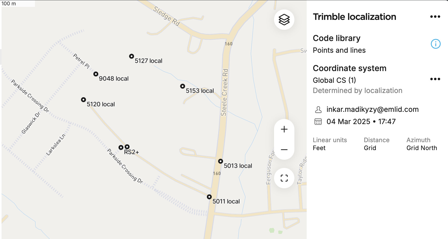
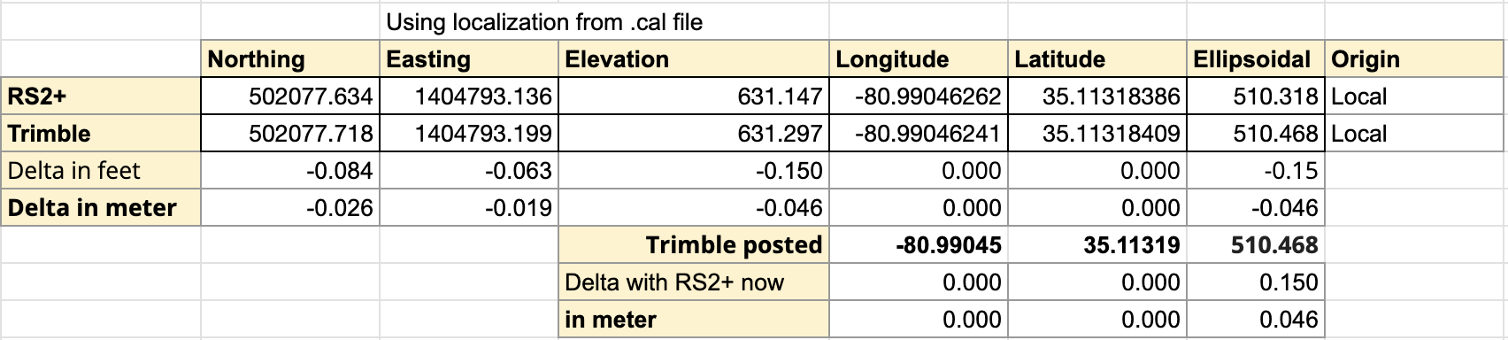
Chris, I’ve reviewed all your data, including the .cal file from Trimble. It contains seven known points with both global and local coordinates in meters. Using that, I applied the localization to set up the coordinate system with the right parameters.
I then imported the local coordinates from both RS2+ and Trimble, and Emlid Flow computed the global coordinates accordingly. The results matched with cm-level accuracy.
It looks like the difference comes from how Trimble applies transformation parameters from the .cal file.
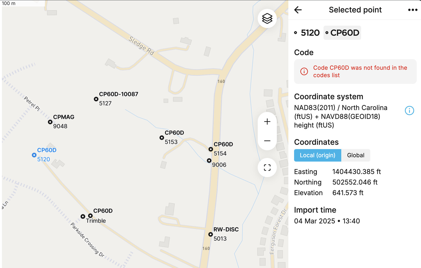
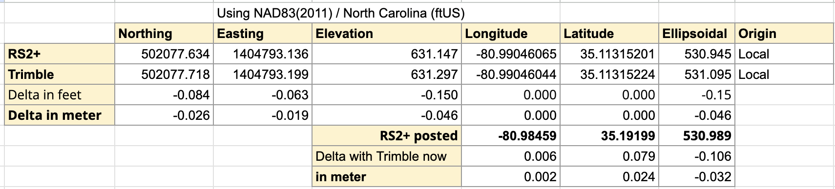
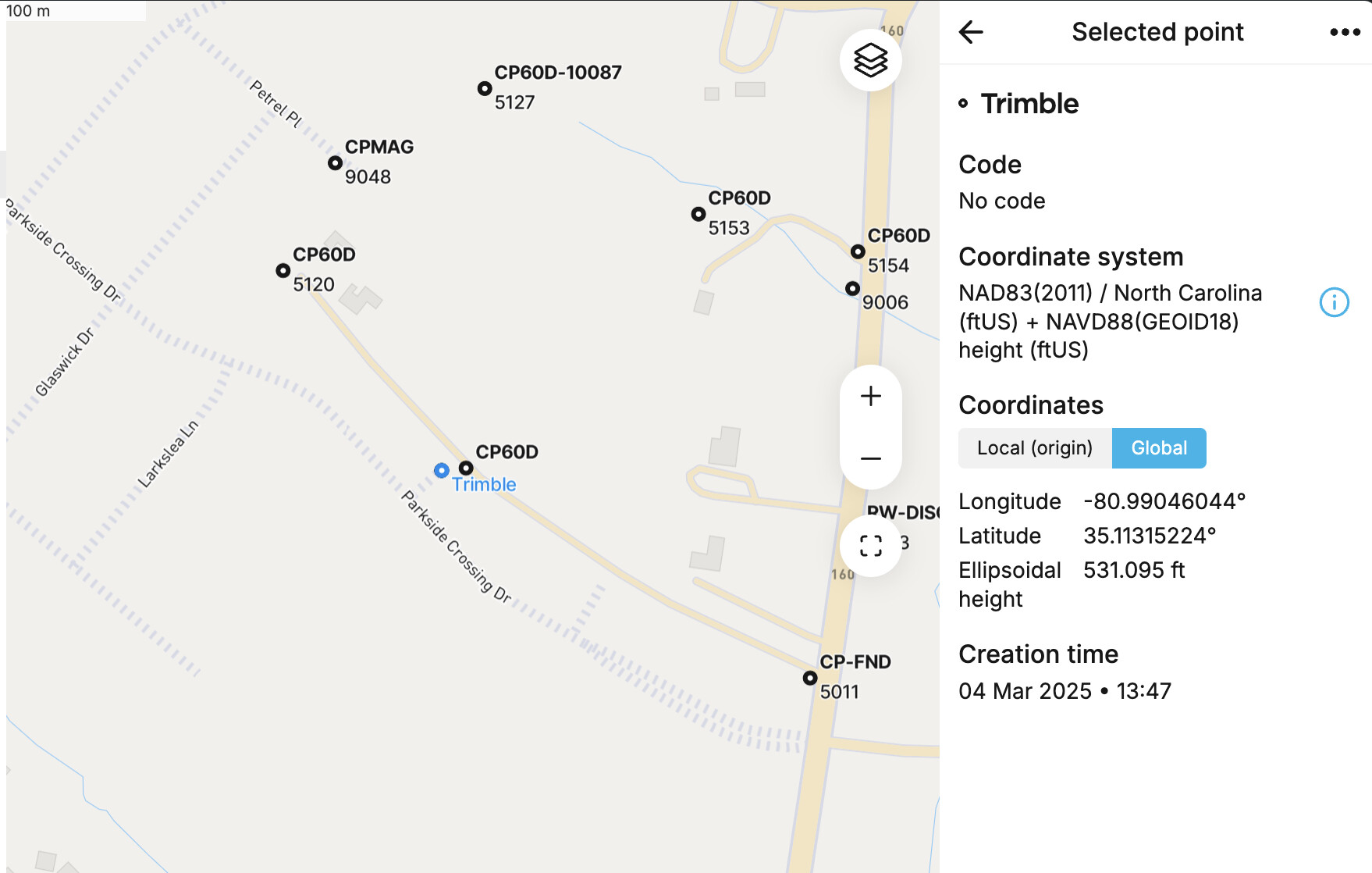
To test this, I created a project in NAD83(2011) / North Carolina (ftUS) + NAVD88(GEOID18) height (ftUS) and imported your PNEZD file. The points aligned well with those in the Trimble dataset.
I was using that coordinate system but have never used the localization function in the app. Should I do this on every project? Can I convert the coordinates from the control points from meters to US survey feet before putting them the project?
For localization, I set up a project in a global coordinate system and added:
Global coordinates as measured points.
Local coordinates as control points.
You can enter the coordinates in meters first and switch the project units to US survey feet later.
Once set up, you can save the coordinate system it creates as a Custom coordinate system for future use. This feature is part of the Survey Plan, and if you haven’t tested it yet, there’s a 30-day trial available.
I also sent you the transformation parameters via PM. If you’d like, you can use those right away to create a custom coordinate system.