What is everyones experience with the power modules for the Edge? I’m having problems with both voltage and current sensing witht the in-the-box module and am exploring using Mauch chips instead as they have a very good reputation.
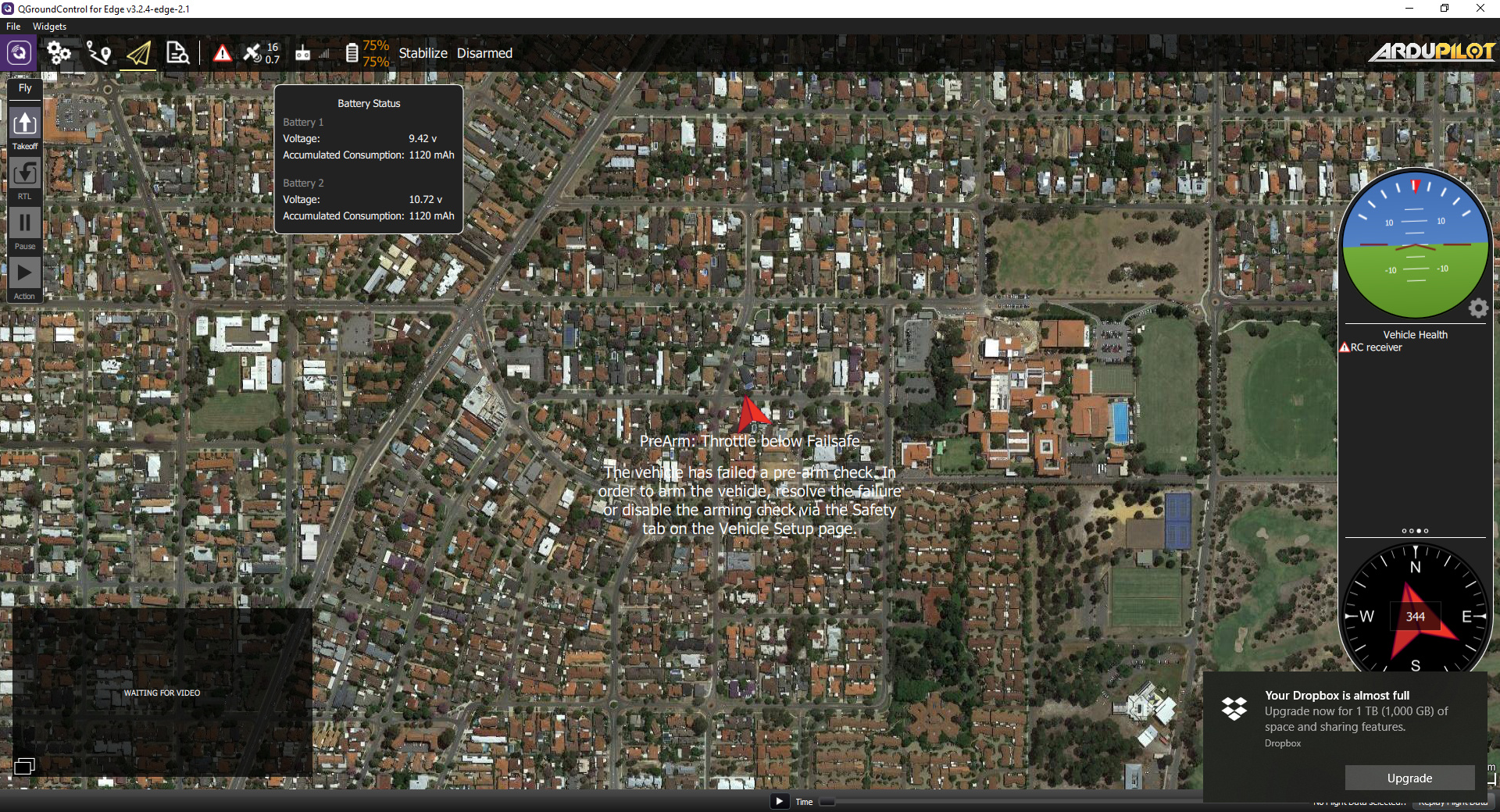
Voltage sensing is very erratic. Sitting on the bench without motors attached it fluctuates from 22-26V. Current sensing appears to be accurate under load, but it is maintaining high readings (30A) on the bench when it should be under just the FC load. So it thinks the battery is depleting rapidly when it’s actually doing nothing at all.
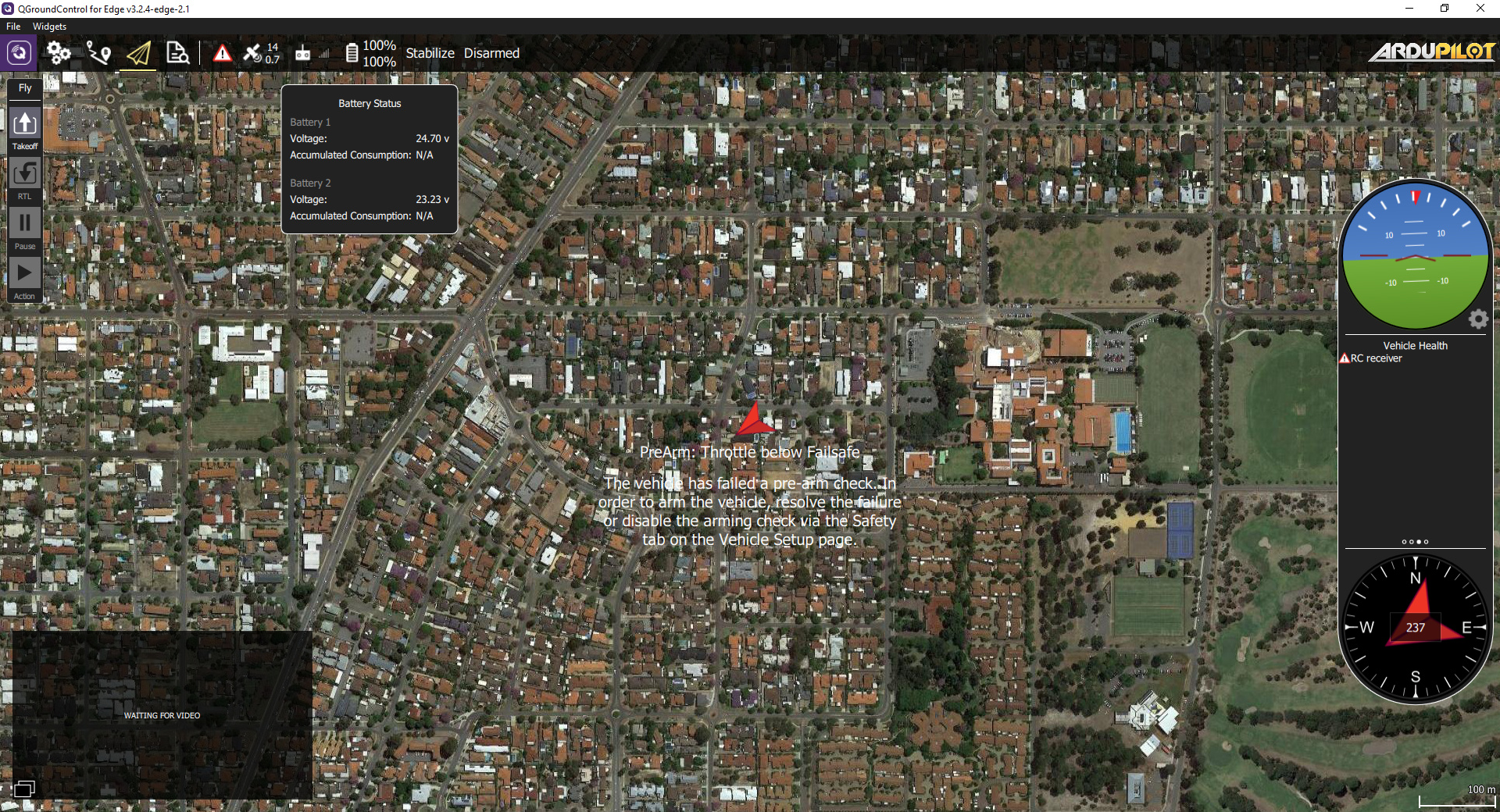
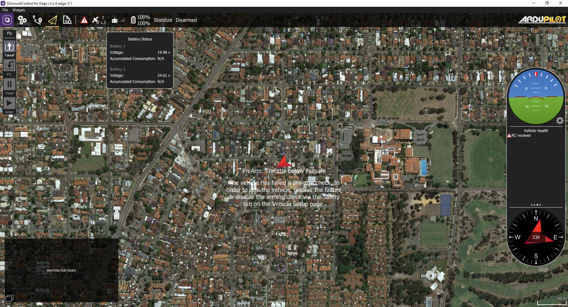
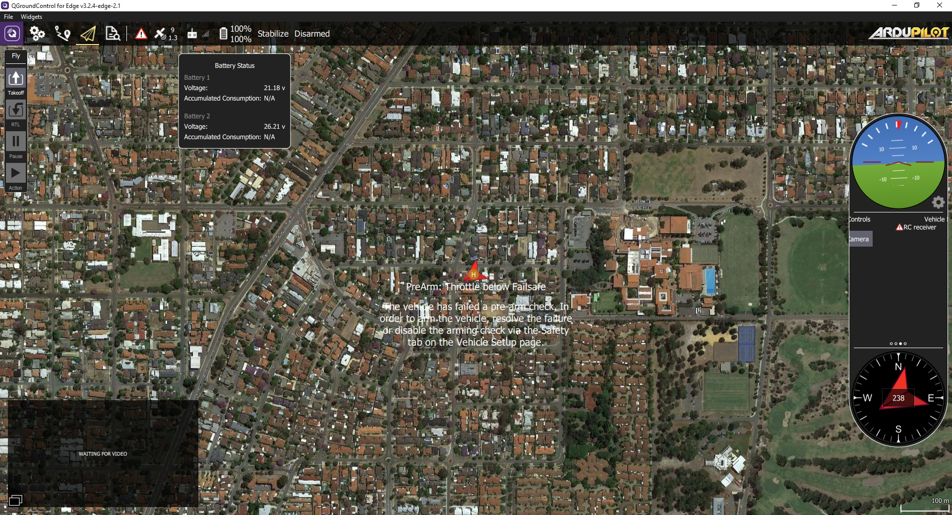
I mapped the 1 power module I have to both display outputs on QGC with the same multipliers and the two values for voltage are different! Both fluctuate from being + or - from the 24V the battery is reading so they do not change relative to each other. I have also double checked my batteries, they are brand new and my voltmeter gives constant readings across the whole of the packs and each cell. Screenshots below is voltage only sensing.
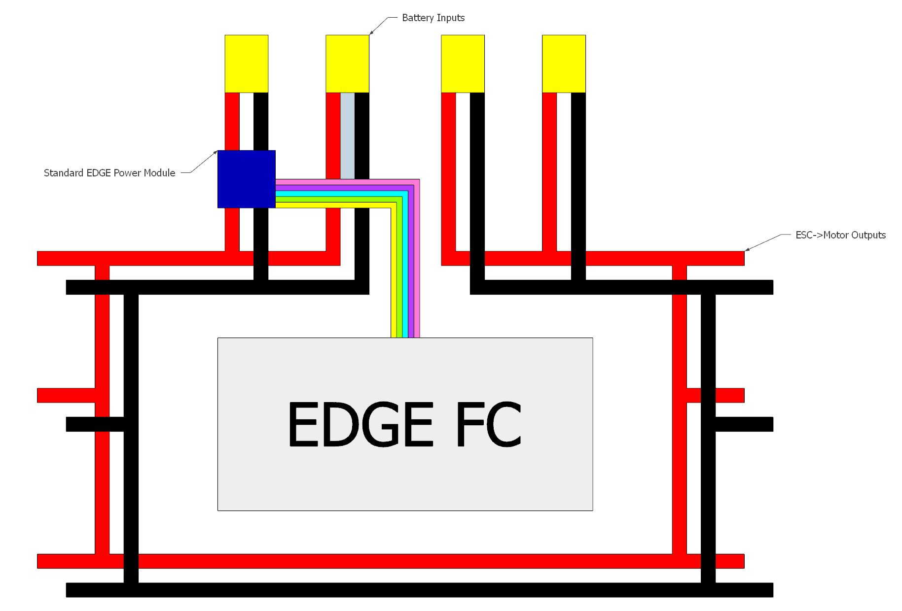
Yes, I know this. The power module that comes standard with the Edge is rated up to 60A without modifying the 10AWG cables attached. Considering 200A (the modules max rating) is still not enough for my system (system motor draw rated to 240A) I decided to leave it as is and monitor only one battery channel which suits the system and power monitor neatly. It should give me at the very least an accurate representation of a single battery in my parallel array and that is good enough for the time being. Data on all four would be ideal, but a battery monitoring system for that isn’t exactly a prevelant piece of hardware. The guys at Emlid have yet to respond to my email about purchasing additonal power modules from them (to either replace or utilize the second power module port) so this is the best I have got currently and it should work as advertised.
However even the single battery channel data being relayed to QGC is incorrect as per my above post, so I have little hope that more power modules will fix the issues. This is why I am considering using a combination of 200A power modules and hubs from Mauch who makes highly respected power modules.
If you have any more relevant feedback as to why I may be experiencing issues please do let me know.
On my Edge, power module is quite fine with voltage. Amp multiplier coefficient had to be fine tuned.
Be aware, if you have more than one battery plugged with your setup that the power module is not protected for reverse current. So one battery on one side and another on the other side could pollute the voltage result.
For your purpose, you can use two modified power modules (with two // batteries on each one).
I have also a Navio2, and I use a 6S-100A Mauch power module with it (4.5kg OctoQuadX).
RMK: Edge unit with Wifi module is quite power hungry…
Is reverse current really an issue in these situations? Theoretically yes it would polute the readings, but how much reverse current would there be when the motors are pulling 50A total at hover? I would assume the effect on the sensor would be quite minimal as the batteries will be discharging at a rate much higher than any reverse current.
Something I failed to mention in my original post is that the values displayed in all the screenshots was with only 1 battery connected. So all the voltage variations I am seeing is purely from 1 power source and somewhat negates the reverse current theory.
Can you please advise any changes to the wiring that would alleviate any possible reverse current. Can you also advise in detail the “two modified power module” setup you mentioned in your last post - I’d be greatly interested in your input there.
The three options I am considering for the Mauch hardware is:
2x200A Mauch power modules straight into the two ports on the Edge
4x200A into two Mauch X2 hubs and then into the two ports on the Edge
4x200A into a singleX8 hub and into one of the ports on the Edge
Let me know any feedback you may have on those setups.
Wiring suggestion with Edge or Mauch power modules: have two batteries in // on each input port of the power modules.
I agree with you. Can you check the battery voltage with a cell by cell battery checker. You could have a bad cell. If not, check the power connector plugs for loose fit at each end.
Have you any information on how difficult it is to remove the leads on the edge supplied power module? I didn’t want to jeopardize the only one I had so I am unsure how likely damage to the board is or the general difficulty of removing the leads.
As mentioned in my main post above, I’ve checked all my batteries with a multimeter, and the whole packs as well as each individual cell are all 100% healthy. One issue I have had with my chargers is with the XT90S plugs I installed need contacts which reach passed the anti-spark mechanism for power delivery, but I removed this as a possibility by testing some other batteries with normal XT60 plugs - same results as before.
Noted. Do you know what gauge cable to use for 200A throughput? The Mauch 200A modules have the same 10AWG as the Edge unit by default.
UPDATE: I reactivated the current sensing through QGC and left it to dual map the outputs. The current draw is rectified on the display output where the voltage is still very much askew (using 3S battery instead of usual 6S)
I also tested the module readings when using one battery on a single port OTHER than the one directly attached to the power module (as per my wiring diagram) and the module still reports current flow. This is particularly puzzling as this should absolutely not be the case with one battery - there can not be reverse current in this instance.
Can someone from @emlid please make comment on the situation.
Could you please connect a single battery to your PM, active DISARMED_LOGGING in parameters, leave it be for a couple of minutes and send us a log to analyze? If you could measure the voltage of the battery beforehand, I’d be grateful. Thanks.
Battery reading on my multimeter was 11.4V (3S). I set DISARMED_LOGGING to ENABLED and the log is from the next boot so it would be enabled from start to finish.
log_30_2018-2-18-14-28-09.bin (5.4 MB)
Attached log had the battery plugged into the one port with the power module. I did a second test with the battery plugged into one of the other three connectors and it kept reading “logging error”.
If you need me to run 6S or connect the radio or power the motors or anything like that to clear the failsafe errors or provide more data just let me know.
Sorry, it’s taken me a while to reply. Could you please send us a little more information?
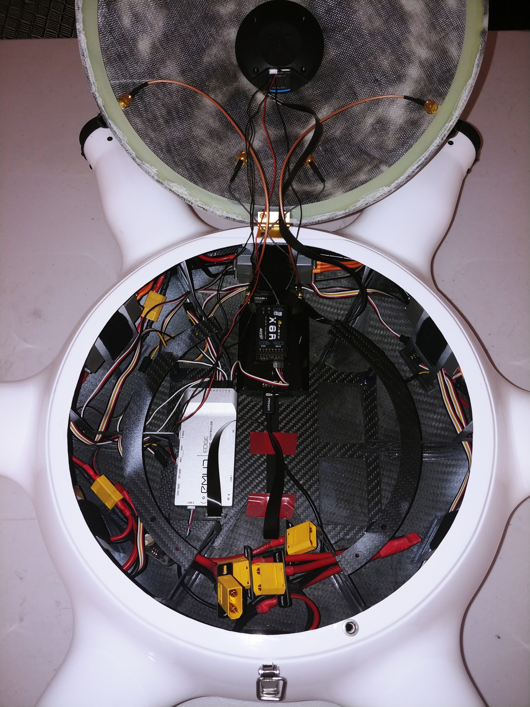
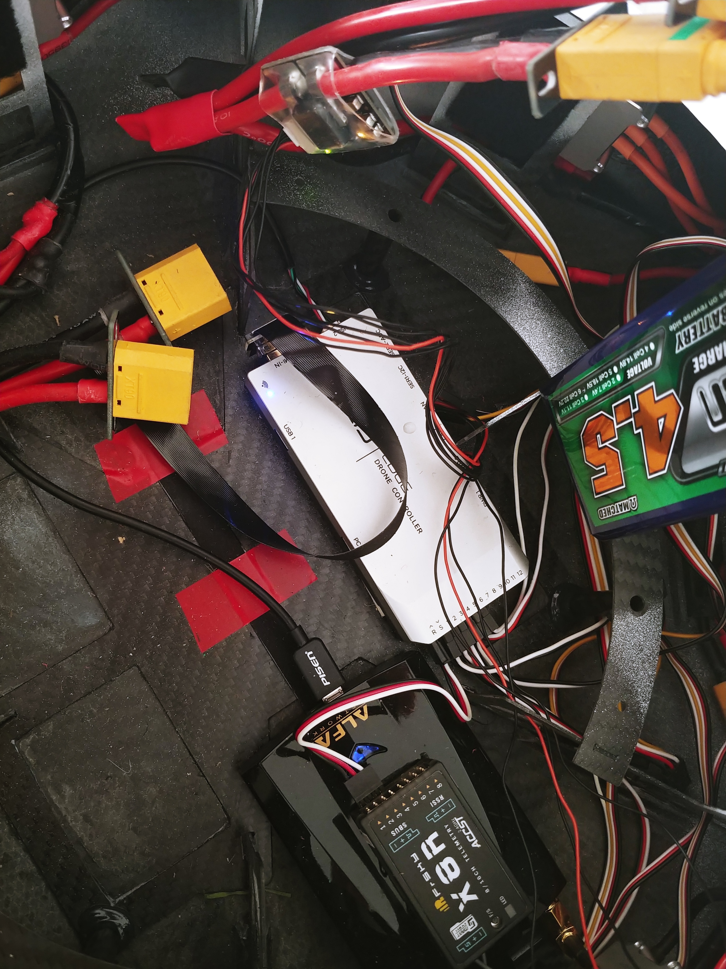
A photo of your setup (with one battery)
Does the LED on the PM light up when battery connects?
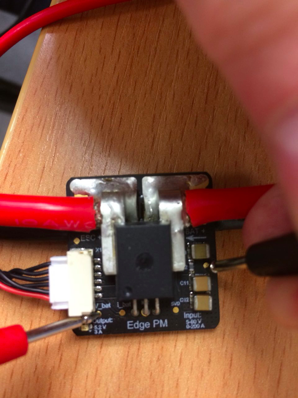
Measurement of voltage with a connected battery between these test pads:
a) GND (between two big capacitors) and V_bat
b) GND (between two big capacitors) and I_bat
Here’s a photo with the shrink tube off. But you can achieve the same without taking the tube off.
As can be seen, all the modules (including PM) illuminate when powered. The copter flies 100% fully functional - have executed test RTL, radio failsafe, other GPS modes and Autotune as well with no issues.
Voltage between the two pins is 1.24V under a 6S battery of 24.6V. I can confirm it reads the same 1.24V when the battery is plugged into one of the other 3 non-power module battery ports.
Unable to upload a .params file or .txt file to the forum, so see the PDF for parameter list. 20180220_EdgeParams.pdf (411.0 KB)
I’m not impressed that defaulting and reloading my parameters is now requiring a whole bunch of sensor calibrations. I was more than happy with everything before that.
Voltage between the two pins is 1.24V under a 6S battery of 24.6V. I can confirm it reads the same 1.24V when the battery is plugged into one of the other 3 non-power module battery ports.
Can you confirm that the voltage across GND and V_bat and GND and I_bat are the same?
I’m also curious if you saw any fluctuations while measuring? Or the voltage was stable (up to some precision of course).