Hi all,
Recently picked up a set of RS2 units primarily for drone GCPs and RTK, but I’m on a side quest of trying to learn how to use them to help verify and as-built our site as it is built.
To preface this, I understand I’m not a surveyor and I can’t use these as-builts for our submittals, but I still think it could be a good way to check and verify progress along the way. For example, before we pour our slab, shoot the corners of the forms and make sure everything looks good.
Anywho, I have the DWG from the architect, which I’ve converted to a DXF via Teigha and was then able to open in LibreCAD. From there, I’ve tried to clean up some of the layers (not sure if this is specific to our architect or if this is standard, but there are a TON of layers, and they don’t all appear to be used) that I’m not interested in. I can verify the scale and positioning against one of the included State Land Survey points and everything looks good.
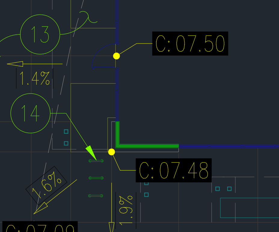
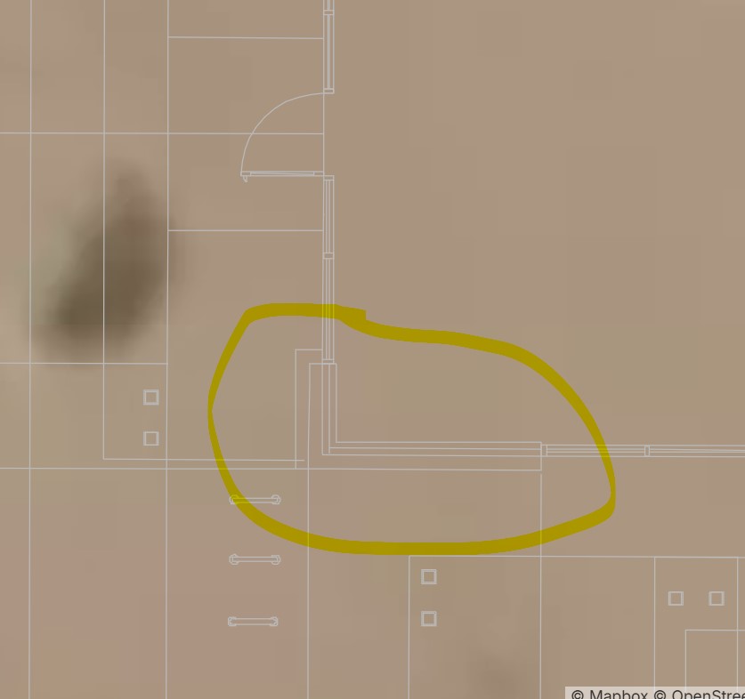
The issue is that once I import the DXF into Emlid, 90%+ of all the lines show up under the “C-ANNO-REFR” layer and it doesn’t give me points or any stake-out ability. The lines also see to be crooked, for lack of a better term. In LibreCAD, everything looks just like it does in TrueView, which is nice sharp lines that are all perpendicular to one another. See attached photos. A bit of searching suggests this might be related to external reference, but I only have the single DWG file which appears to have everything within it.
I’m hoping to find a workflow where I can use our PDF plan sets to create backgrounds or layers from, that way we can check foundations and the such specifically, since they aren’t shown on the CAD file. I’ve tried exporting them as a TIF and georeferencing them in QGIS based on wall corner coordinates from Libre, but trying to convert it from a raster back to a DXF is proving to be pretty difficult. The PDF drawings we have are vector based, but I can’t figure out how to reference them correctly and then get them into Flow.
I’m suspecting this is a case of needing to pay for expensive software to reduce the amount of converting back and forth and jumping between software, but this is all out of my own pocket at the moment, so I’m trying to lessen the burden as much as possible.
I understand this is likely far more in-depth than I can ask to be explained to me, but if anyone has any advice or tips, I’m all ears.