I am a new owner of the RS2+. I went out yesterday and took some points around my yard connected to NTRIP as a base. I now am attempting to bring those points into my Civil 3D drawing, which is not going great.
I have many failed attempts at this, but the closest I have gotten is doing this: I export the data from Emlid Flow as a .dxf file. For some reason I cannot open that .dxf file from within my CAD drawing. However, I can open it on its own, and then I have a nice drawing of all my points I took with the RS2 showing up as a .dwg file within CAD.
Next I try to attach my CAD drawing to this points drawing using XREF. I then bind the drawing together, and it comes so close to working, but unfortunately the two drawings do not line up. The points are all far away from where they should be.
In Emlid flow, it shows that my units are in feet, and I am using NAD83(2011) / Vermont coordinate system. In my original drawing, I am using NAD83 Vermont State Planes, US Foot.
When I initially open the .dxf file, there appears to be no coordinate system associated with it, so I change it to NAD83 Vermont State Planes, US Foot before attaching the other drawing.
I am not sure what the best way to import the points is, I am just using the only way I was able to get them to import at all.
What is the actual misalignment? Is the CAD in surface coordinates and requires a scale factor? This I common in our area but is usually easily rectified by a horizontal shift. the actual % of scale of the design is insignificant. Is there a localization in place. These are worse because they can provide a scale factor that is not equal to the predefined scale factor but can also introduce rotation.
Not only am I new to GNSS receivers, I am also new to CAD. So I am not certain what the actual misalignment is, I only know it is misaligned by quite a lot of distance, both horizontal and vertical.
I am not sure how to answer your questions about whether or not the CAD is in surface coordinates or if there is a localization in place. All I know is that the original CAD drawing is in NAD83 Vermont State Planes, US Foot, and the Emlid files were captured in NAD83(2011) / Vermont coordinate system.
Not sure how or why they don’t align.
Thank You
Edit: Maybe I should also mention that the original CAD drawing does have multiple files (ortho view, lidar contours, and parcel boundries) all aligned perfectly with each other.
That’s a good thought. I checked and it says: “As of February 15, 2013, the Vermont CORS are referenced to NAD 83(2011) epoch 2010.00. These coordinates are employed for all data products, both raw and real-time.”
That much sounds like a difference in datum. Are you using EPSG# 6590? Do you have any documentation of what the CAD was generated with?
Typical scenarios I see,
+/- 30ft - arbitrary base point
+/- hundreds of feet - scale factor (at least in Texas because or northings are in the 10-million range)
+/- tens of thousands - datum
I am not sure if I am using EPSG # 6590, as I have to figure out how to check that out / what it means.
I did want to point out that I just realized the elevations are perfect. My original CAD drawing’s Lidar elevations match perfectly with the Emlid data. Not sure if that means anything to you.
I’m not sure what you mean by what the CAD was generated with. I do wonder if the problem could be that I cannot import the .dxf file directly for some reason, so I cannot set up the CRS in CAD before hand. Instead all I can do is double click the .dxf file and just let it open up itself in CAD.
EPSG 6590 is the standard NAD83(2011) Vermont coordinate system. Surveyors use all different types of coordiante systems for different reason but most try to stick with this version. The original survey should determine how the CAD was positioned unless someone moved it after the fact. In Texas we have 5 zones so it’s easy to be in the wrong one if not paying attention. I work in 6578 or 6588 and they have two different coordinate ranges despite there being overlap. This is horizontal datum BTW. Sounds like you got the right vertical and geoid.
I see. Well since it appears there is only one zone for Vermont, and everything I have produced says it is in NAD83(2011), I’m not sure why it wouldn’t be in that.
I wonder if there is a better way to import the data. If you don’t mind, I was wondering what method you use to import your Emlid data into CAD…
OK, that does looks familiar, haha. Is that something that came up in Emlid Flow as I was setting up my receiver? I can’t remember where I’ve seen that screen before.
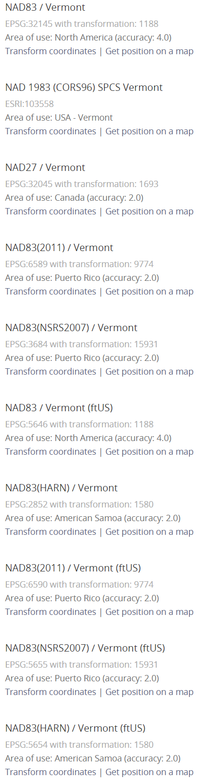
Hmm OK. Well I suppose there is a chance I chose 5646 instead of 6590, as they are both NAD83(2011). Apparently the difference is that one has accuracy of 4, and one of 2, whatever that means. That doesn’t seem to me like it would make my map be off by a million feet from that difference, but I have no idea. I will give it a shot tomorrow to see if selecting a different one makes any difference.
As far as the CAD, I created the map myself, importing data from Vermont’s open data portal. I imported 3 different files that all line up with each other. Lidar elevation contours, ortho imagery, and parcels. Looking at the metadata of the parcels this is what I see:
Horizontal_Coordinate_System_Definition:
Planar:
Grid_Coordinate_System:
Grid_Coordinate_System_Name: State Plane Coordinate System State_Plane_Coordinate_System:
Horizontal_Datum_Name: North American Datum of 1983 Ellipsoid_Name: Geodetic Reference System 80 Semi-major_Axis: 6378137 Denominator_of_Flattening_Ratio: 1 / 298.25722210
Not sure if any of that means anything to you haha, no worries if it does not!
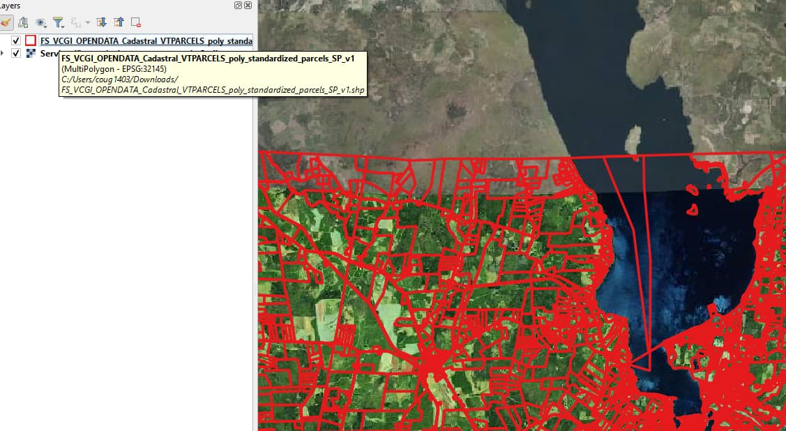
I went ahead and downloaded that layer. It loads perfectly in QGIS, aligns with the orthomosaic basemap I put under it. The reported CRS is EPSG:32145, which is called NAD83 / Vermont. It’s a metric system so no wonder there’s a massive shift when you import that data and tell your CAD that the values should have an origin and units from an imperial system.
I’m guessing that all the data is in that same system so you now have to decide if you want to transform your survey data to that same CRS or if you need to transform the state data to your CRS.
Maybe your CAD can do on the fly transformations, in which case you can just skip transforming anything and just define the correct CRS when you import the layers.
I had the units thought in my mind but that’s a new scenario to me. If that happened to us we’d be in Peru, lol. Sounds like the CAD file needs to be rectified.
Last night I had actually looked back at my post above with the data, and noted that it said:
After thinking about the codes michaelL talked about, I realized that something wasn’t lining up. I went back into the Project Coordinate System Tab in Emlid Flow and searched ‘Vermont’. This brings up all the options available, and I noticed that one of them happened to mention 4400 in description (*sidenote: it appears to be impossible to do this from Emlid Flow 360). I chose that CS and went out and retook the same points. Upon importing into CAD, these points do end up in the right place! Although it is true that they are metric. Which means I could either convert the elevation to feet, or try to find a different CS that works, or use different files for creating my CAD.
I’m saying that in Flow 360, when I type ‘Vermont’ into the search bar, only one result populates. When i do the same in the mobile app, I see like 10 or so.
I am using Civil 3D. I am not sure about the geographic coordinates, but it would seem I am close to getting everything resolved now anyways… (i think, fingers crossed)