


But experimental findings of a new insight will bring about a revision in textbooks. Experimenters always have the last say, and needless to say, I am not using state of the art GNSS equipment of 1990s vintage.
1 Like
I do occasionally, we have two old Trimble 4700 receivers. They are still great receivers and have given us years of service. I occasionally use them for static when needed for large networks however it’s a pain in the ass to modify the logged files due to Trimble’s planned obsolete of the receivers.
I even have an old Leica MX 9400R 12 channel L1 receiver from 1996. This was originally manufactured by Magnavox, imagine that ! I haven’t used it in about 2 years, great receiver with very clean data when using a choke ring antenna.
We currently have all Javad gear in use. These are the best scientific GNSS receivers for land surveying and geodetic networks.
1 Like
FWIW - A person from NOAA Federal indicated…
“The ARP height for the vast majority of CORS is set to zero…to confirm this, check the RINEX file for any CORS that you download; if there is any vertical offset (aka ARP height) it will appear in the upper Comments portion: ANTENNA: DELTA H/E/N. The H component would indicate any non-zero ARP height.”
1 Like
Yes, correct. And not just the US, globally.
Thats because - as above - it’s all about the bottom of the antenna.
It doesn’t move, the phase centers however are constantly moving about with the different frequencies and angles of incidence (both azimuth and inclinations). At any point in time you could conceivably have 70 or more phase centers on the go, one for each satellite and each of it’s frequencies… and they all keep shifting.
Thats why you may see loose references to quoted phase centers as being “average”. If you did a 12-hour observation for a complete constellation orbit they may get close to averaging out - but only if you were central to the orbits of the constellations you were observing. If you weren’t, and/or only observed an hour or so, they obviously won’t and will be off some amount.
If the rover and base antennas are identical, and the baseline very short so that the angles of incidence from the satellites remains identical then those effects cancel out and life is good for differential.
Otherwise, in most other cases it’s the software that works all that out for you, and why you just need to focus on that ARP at the bottom of the antenna.
3 Likes
I’m aware of NGS offering files of absolute antenna calibrations in both ANTEX and ANTINFO formats, and recently aware of errors of up to 10 cm in height when mixing of antenna types. I would assume CORS based equipment can utilize an absolute file, but unknown if a GNSS Receiver like a mosaic-X5 can—since its user config menu only shows H/E/N.
About a 41 hour Rinex recording was created for the OPUS evaluation, which was used to determine the difference in coordinate offset from the ‘CORS’ to rover evaluation via NTRIP.
No.
I don’t know what your source is (maybe this paper?) and if you fully understood it but the lesson you should take out of all this is simply to correctly define the antenna code info when you submit raw data and measure to whatever reference point you wish to get a result for (ARP or ground). All calibrated antennas are comparable, precisely because they have been calibrated.
1 Like
I should have added to that “10 cm in height” comment if “antenna-phase-center variation and antenna-phase-center offset” are not properly modeled. NGS’s opinion on this topic of mixing antennas.
Thx for link…
Published in late 2013, and under this condition—When using TBC software without applying PCV correction factors…Leica receivers on both ends of the [27.3km] baseline;—they noted
In all cases, changes in easting component are small and in the range of 0.002–0.004 m.
which is what I observed over 20km baseline (2mm difference). They further noted that height and northing components were greatly affected, and I observed this in northing (27mm), but a small amount (3mm) in Ellipsoidal height difference.
Note - Base station is CORS like, and rover’s OPUS evaluation was based upon a calibrated antenna at zero ARP.
I would conclude this textbook equation,
Horizontal Accuracy = 0.8 cm + 1 ppm × Distance
is more relevant to the northing component.
Another issue most users don’t consider is the north orientation of antennas/receivers. NGS uses this as a reference in their calibration.There is a mark or direction noted for all calibrated antennas from the manufacturers. Emild’s is the MMI.
Antenna/receiver orientation is critical in post processing of precise geodetic networks as well as use during RTK.
2 Likes
Spot on, here’s a work in progress example:
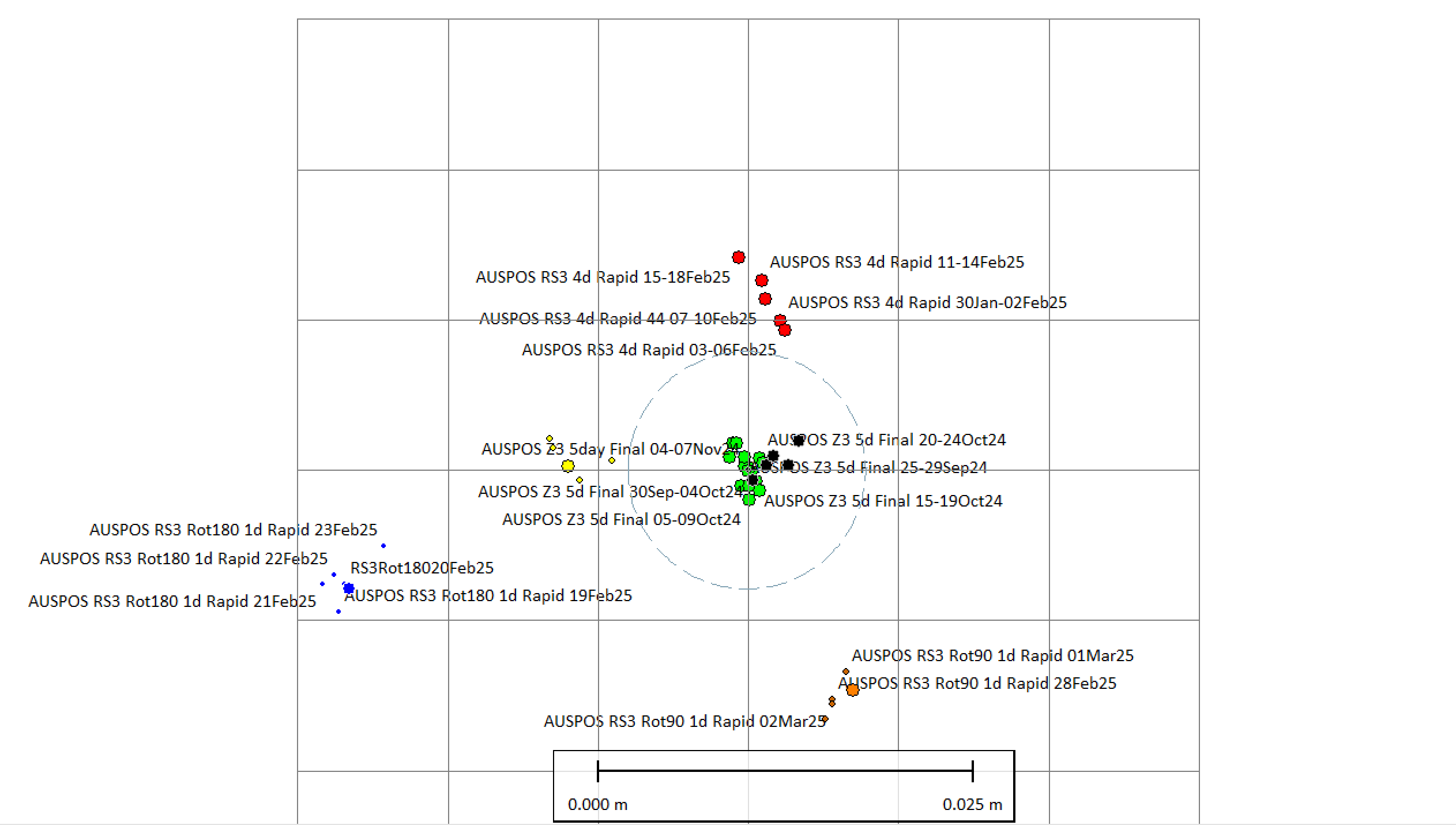
The center of this 1cm grid is my reference mark. It’s calibrated with a NetR9 and both a Zephyr Geodetic 3 with a total of 15 x 5-day observations AUSPOS final results (green dots), and Zephyr Geodetic 2 with 6 x 5-day observation AUSPOS final results (black dots). So you can see I’m pretty confident its accurate.
The circle is a visual representation of the 5/8" antenna mount.
So to the RS3.
The Red dots are 5 x 4-day observation AUSPOS results with the RS3 oriented MMI (panel) North.
The precision looked OK but accuracy not as good. So got me wondering about the MMI reference and decided to go around the clock (literally) to check:
Orange dots are RS3 rotated 90 degrees, panel facing East. The small dots are 4 x 24hr observation AUSPOS results, larger dot a 4-day observation AUSPOS result (rapid).
Blue is 180 degree rotation, panel now facing South. 5 x 24hr observations & 1 x 4 day observation AUSPOS results (rapid).
Yellow dots rotated 270 degrees with the panel facing West. 4 x 24hr observations & 1 x 4-day observation AUSPOS results (rapid).
The consistency and precisions of each are good, but the variations in accuracy can clearly be seen. Worst case is 180 degrees where it more than doubles, picking an additional +1.6 cm.
Interestingly the 270-rotation fared better, and the jury is still out on this.
5 Likes
Thanks @Wombo !!
Thx for the example, but on an OPUS note using the same RINEX file and inputting two different calibrated antenna types (two separate evaluations), I found deviations of 5mm Lat, 3mm Long, and 30mm Ell between a $3k antenna vs $300.00 antenna.
Two Sidebar Questions Below - I took a newbie dive into GPS last year via here/there internet sites, and mostly/fully grasp concepts like OPUS, RINEX, reference frames, tectonic plate movements, EPOCHs, NCAT, and HTDP transformations.
Emlid Studio - Last night, first time user, another head spin:-)
-
CORS to stationary rover - When done on 2025/03/20, does the rover’s coordinate shown need to be transformed again—need to be in NAD83(2011) reference frame.
-
It appears a limited set of antenna phase center offsets (PCOs) are available in Elmid Studio. So when using a Reach M2, and a Harxon HX-CGX611A antenna, PCO insertion is not possible. Is there a way to include this antenna?
thx…
If you corrupt a RINEX file with incorrect data, your results will be incorrect and completely meaningless. Same for splitting hairs with a single file/observation, insufficient sample size with a random outcome and equally meaningless. Committing both atrocities at the same time is not a good look.
Rover results will be in the same datum as the Base, it’s simply differential.
Your Harxon antenna is in the ATX file and available to Studio, IGS designation HXCCGX611A. But not the M2.
C:\Program Files\Emlid Studio\resources\igs20_2335.atx
If a rover’s RINEX file has this in header info,
TRM57971.00 NONE ANT # / TYPE,
then studio will use this antenna’s specs.
Since Trimble’s/etc antenna info will be used, I suspect M2’s RINEX file header info could be altered so the PCOs for the Harxon antenna are included, but…yeah but…I might assume M2’s suggested antenna to buy is programmed in M2 (Reach M2 GNSS antenna phase centers’ offsets for L1 and L2 are 0.035 m and 0.037 m respectively. as default values.), but this antenna is not listed in ANTINFO
Hello Emlid, how about a new feature in M2, where the user manually configures a calibrated antenna, or downloads the file into Reach R2?
FWIW: ANTINFO info explained here: SEE: 3.3 FORMAT OF INDIVIDUAL ANTENNA CALIBRATIONS
Tidbit - When I did a CORS to a static rover, baseline was 73.6km, so I expected rover’s coordinates to be skewed.
thx for tidbits…