Hi, I am confused about the picture which shows connection between ESCs and Power supplies.
And here is a question…
Q. According to this scheme, the re and black wires on all four ESC’s connect to the Power Module. But the power module only has two plug ins. How can four wires be inserted into each plug in on the power module?
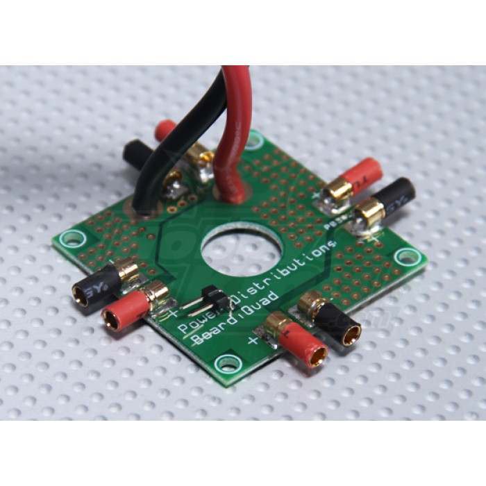
It is just a way to go from 1 cable pair in to 4, 6 or 8 cable pairs out. You can make it as simple as solder the cables together or buy a power distribution PCB. They also come in different types. From very simple with just traces and solder pads, to more complex with voltage regulators for different applications. Here is a picture of one:


