I don’t have the Navio board yet, but here is my take on flight controller software:
Still WIP, I already started porting it to the Navio.
It’s still a few months away from the first release.
I don’t have the Navio board yet, but here is my take on flight controller software:
Still WIP, I already started porting it to the Navio.
It’s still a few months away from the first release.
Jean, that’s an amazing idea, I hope that it would be really useful in research and education.
Hello Lars,
do you have this shield for sale?
I am highly interested in one of this, as I am looking forward to get on to RPi and out from APM.
I dont see any other post about your autopilot progress, do you have related activity in other forums? I would really like to read more about your project.
Thanks!
Hey Allan,
Thanks for the interest in the sensor shield. I don’t have it for sale but I can give you a parts list as well as the EAGLE and or gerber files so you can have one made if you like. I had mine made through OSH park (https://www.oshpark.com). I made a few revisions to the board (a few additional resistors I forgot and some layout work) and I’m also slowly working on a shield+ for the NAVIO+.
I’m using the shield outside of APM, actually I don’t use APM at all, for data collection only. My research requires a few additional measurements that NAVIO doesn’t provide so I designed this shield to collect those. The additional measurements are airspeed, angle of attack, side slip angle, RPM, static pressure (static pressure from the onboard barometer may not be equal to true static pressure since the pressure inside the aircraft may not be equal to the pressure outside) and a real time clock. AOA, side slip, and airspeed are measured using a five port probe. This was one that I built myself and calibrated in a wind tunnel.
Don’t have too many other forum posts, just some random posts on getting some of the NAVIO sensors setup for my particular problem. As I mentioned before, right now I’m only using NAVIO and shield for data collection but plan on adding some controllers to it in the future for parameter identification maneuvers as well as stability augmentation. Right now I’m tied up in the theory portion of my research and haven’t had a whole lot of time to work on hardware. Hopefully this helps!
That would be amazing, if I can help you on anything let me know, I am working on a long range skywalker X8 project Which will be launching by the end of the month.
I am trying to find a way to PM you with my email
Hello everyone!
For my thesis I’m developing an infrared positioning system for indoors.
These are the infrared waypoints:

I’m waiting for the navio+ and the quad copter, for now I’m testing it with this case:

The results are shown in a web interface:

I still have to deal with the APM code to be able to use the positioning data.
@marc That looks very interesting. Will this be a monocular solution? SLAM based?

Quanum Venture FPV QuadCopter
Navio+ and RPI 2
I changed to 9"x47 props and it runs great. About 15 minutes of flight time using 4000mah 3S 35C Lipo.

Is this a Quanum Venture?
@mfm Yes it’s a monocular solution, I use the Raspberry Pi NoIR cam. I didn’t know the SLAM technique. My approach is much simpler and it requires less computational power.
Very nice project. What is the precision you hope to get? I assume it’s only limited by the camera resolution and the number of infrared points in view.
Can you infer the position of the points by moving the camera in a predefined pattern and track the points in view?
PS: Are you from Catalunya?
@marc A lot of SLAM VO solutions are capable of running on smartphones etc. Something that might be interesting to you is: GitHub - uzh-rpg/rpg_svo: Semi-direct Visual Odometry. It’s a VO solution that is targeted at multicopters. They actually run this on a Odroid. The performance is quite impressive:
")
The solution is aimed to be used as part of ROS but can also be build as a standalone lib.
@jeanleflambeur Thanks! Yes the precision depends on:
I didn’t do any accurate precision test but I suppose it’s in the order of few millimeters when the beacons are close enough.
Sorry but I don’t understand your second question. From each waypoint found I get a position & heading of the camera, if I get more than one waypoint the position (specially height) and the heading can be improved.
Yes I’m from Catalunya (Barcelona).
@mfm Thanks for the info! It’s very impressing, I could use it when there are no waypoints in view.
Maybe I got it wrong but as far as I understand, the system works like this:
My idea was to replace step #2 with two other steps:
2a. With the camera at 1m away from the floor and rotate it 360 degrees
2b. With the camera at 2m from the floor, rotate it 360 degrees again
At steps 2a & 2b you can record the position of the beacons - as the camera sees them - and, knowing that the camera rotated 360 at 2 different heights - you can infer the relative position of all the visible beacons.
I don’t know if this is doable or usable though ![]()
Very interesting project anyway.
@jeanleflambeur Yes, you got it wright!
But now I’m improving the system. It will only need the position of one waypoint (the master), then the system will infer the position of other waypoints as they appear.
Example: 1 master waypoint and 2 slaves.
I see - that is an even better idea!
This project of yours makes an indoors quad way more attractive 
Congrats and keep us posted
@mfm @marc There is also some great work done by TUM:
")
Their latest development is called “Large-Scale Direct Monocular SLAM”
Hi @larssoltmann ,
How did you post processed data in MATLAB ? Can you please tell me the steps for it . i really need to know to where to start from. I am still learning things 
Thanks a lot
No problem Vishal, I’ll list the steps that I took in MATLAB based on the research requirements. Depending on what information you are trying to back out you may need to modify or add steps. The research goal was to determine power required from dynamic maneuvers using maximum likelihood estimation. This provided estimates for the lift and drag model regressors which were then used to calculate power required. A good reference for the MLE process as well as aircraft modeling can be found in Aircraft System Identification: Theory and Practice by Vladislav Klein and Eugene Morelli. The general steps are as follows:
Preprocessing - This includes: segmenting the data into individual runs, correcting for IMU offsets, correcting for CG vs accelerometer position, converting pressure transducer data into airspeed, altitude, angle of attack, and sideslip, calculating thrust, calculating control surface positions, applying any necessary low pass filters, etc.
Definition of aero models - I used the standard linear lift and drag models.
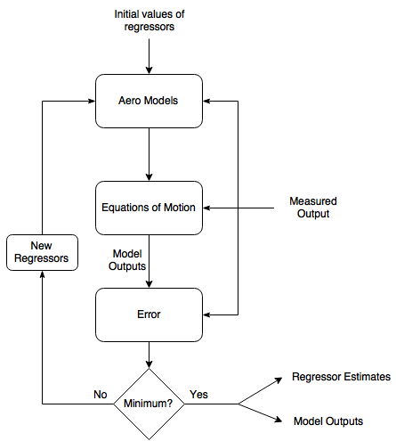
Regressor optimization - This is the meat of the estimation process. The main goal is to minimize the error between the measured values and the model outputs by selecting the “True” value for each model regressor. This is achieved through optimization. The user provides the optimization routine, in this case FMINCON, with an initial guess for each regressor. The optimizer then solves the aero models using the measured data and provided regressor values. The aero model outputs are then fed into the equations of motion along with the physical properties of the aircraft to determine the states (accelerations, velocity, angle of attack ,etc). The error between the estimated output and the measured output is calculated and then the next best guess for each regressor is chosen and the process is repeated. The process stops when the error between the modeled output and measured output is at a minimum. This is slightly simplified but covers the basics.
Post processing - From here you can use the optimized regressors to estimate additional properties about the aircraft, like power required, or use them to develop a simulator.
I included a flow chart of the optimization process to aid in visualization. Hope this helps.