


Oh…OK, I really want to apply this configuration, but now I really busy with my job, I would really hope the reasult is better.
There’s lots of chatter in a few threads here which brought me to ask my (other) self the question, “How could we troubleshoot a situation when we are using a radio link and where the grey bars of the base are not showing a continuous, good signal?”
At the office, there is a short radio range and everything can appear good.
In the field, the conditions are often less than ideal, and when things aren’t working, we are more concerned about capturing the particular data set than doing radio troubleshooting.
I suppose that one could do his RTK work while also capturing raw logs for post-processing. If the RTK results are bad and the post-processing is good, that would shift the blame to the radios.
Currently this can be accomplished with 3 Reach devices, or by using my command-line workaround, or by waiting for this feature in Reachview, which, by the way, is on ReachView’s roadmap.
If the blame is then shifted to the radio, then another thing that could be done is to record a set of good quality base and rover logs, then play them back in real time with the RTCM3 portion going over the radio link and see what happens to the quality of the solution data versus the post-processed original. Of course the logs could be compared for quality as well.
Another idea which could be implemented, is to send a file with known contents across the radio link, and compare it on the other end. For example, a copy of this file is on each Reach device. Say the file is in RTCM3 format and it contains 100 RTCM3 messages. The file is is sent over the radio link, at a certain pace, to another Reach. There it is compared to the original file and scored for the number of identical RTCM3 messages received, and for the correct timing of those messages. This whole process could be automated with, let’s say, a “receive RTCM3 test file” button on the rover, and a “send RTCM3 test file” on the base, and a percentage score displayed at the end of the test. Something like this might even be paired with another feature for changing radio settings ![]()
(@Juan_Diaz I wrote this post before I read of your latest tweaks, so I am hoping your tests turn out to be successful!)
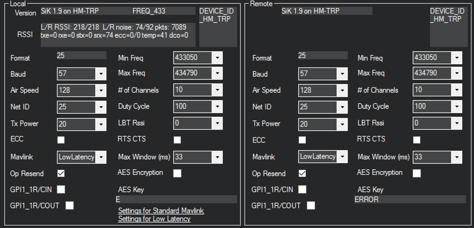
Today’s test was quite successful. Although I have experienced previously that one days configuration that works, may not work a different day in similar conditions. I would love to hear extra feedback if anyone tries the same or other configurations. Again, this is what I configured in the radio (I am focusing on that, because I have not had issues with graybars dropout using wifi connection between modules and my cell phone as a hotspot):
First, the results: I tried two different times and was able to obtain fix within less than 1 minute. I still saw some of the gray bars dropout but I think not as often as before, and they recovered quickly. In fact, it did not affect the ability to obtain first float and then fix. It did go from fix to float a couple of times but I am not entirely sure that it is due to the dropouts. In all cases, fix was recovered within 3 seconds.
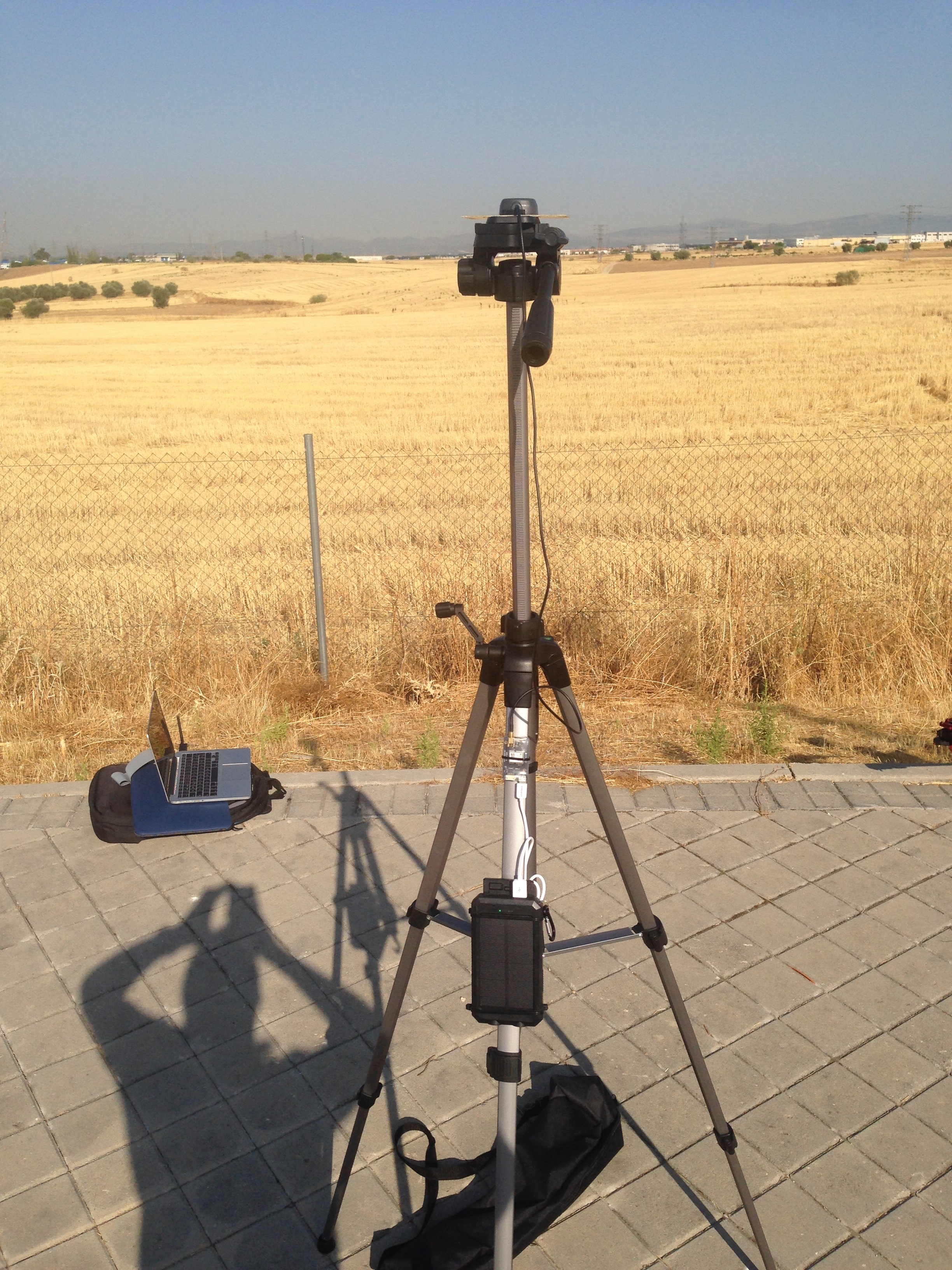
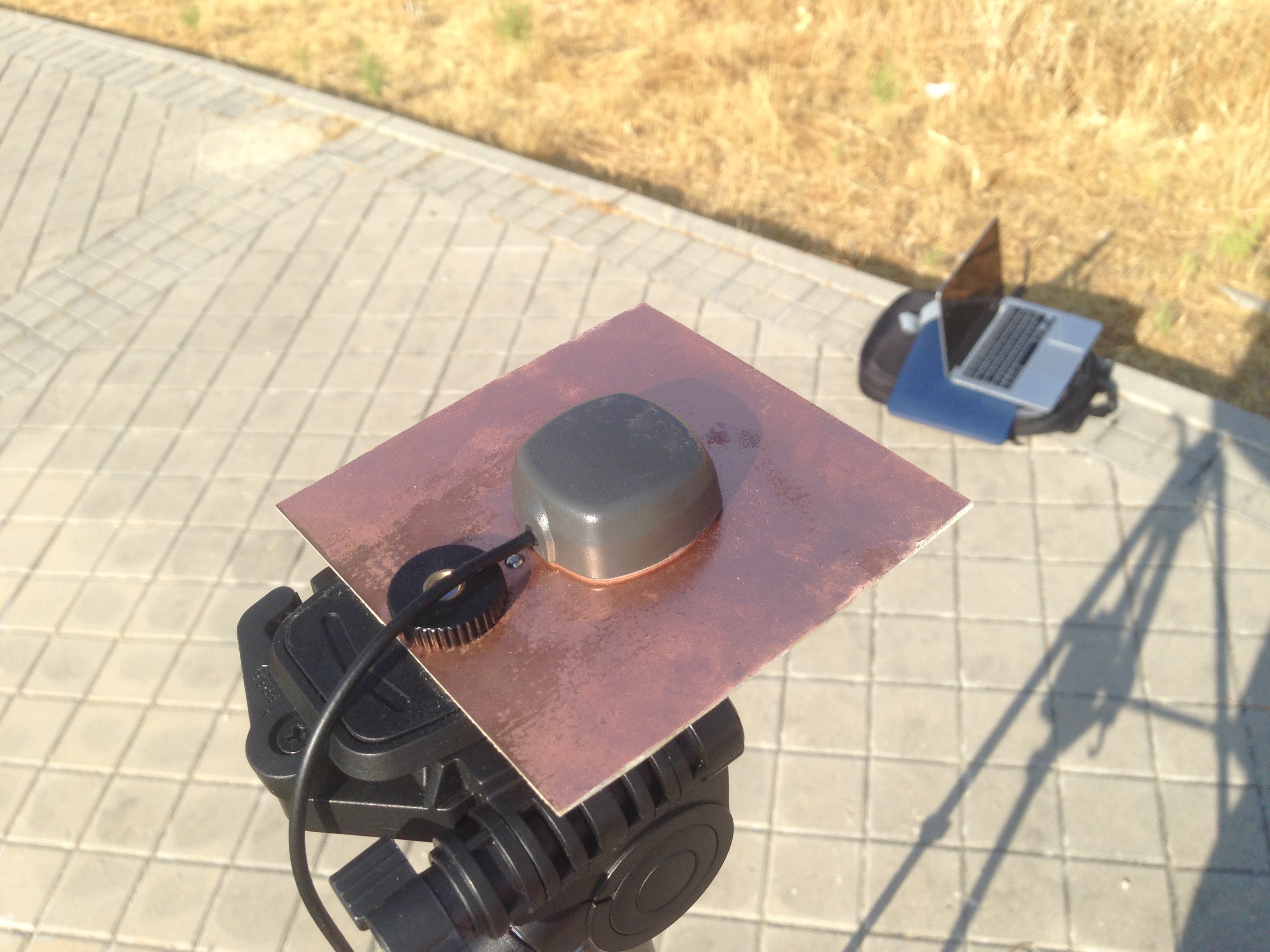
My setup, as mentioned before was using my cellphone as a hotspot for PC and both reach modules, the Mission Planner obtaining corrections from base using TCP and GPS inject into 3DR 433MHz radios. The base module is on a 1,7m tripod and powered by an external USB battery pack:

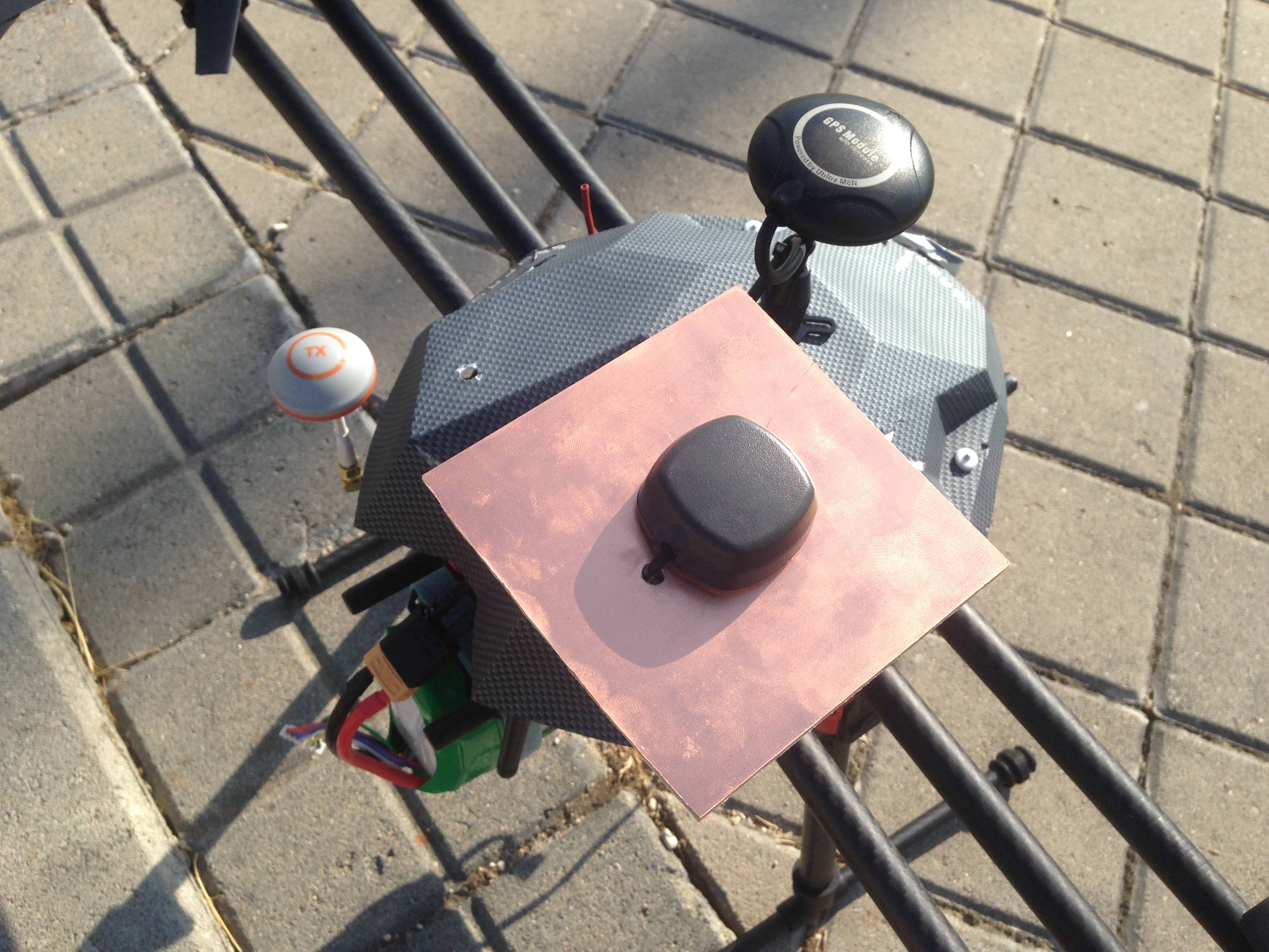
The rover module is inside the drone canopy, with the antenna on top of a mast I made with gopro brackets, and at the same level or slightly above the main GPS antenna. (I know the canopy is in bad shape, its the one I use for testing antenna placement and drilling holes
 )
)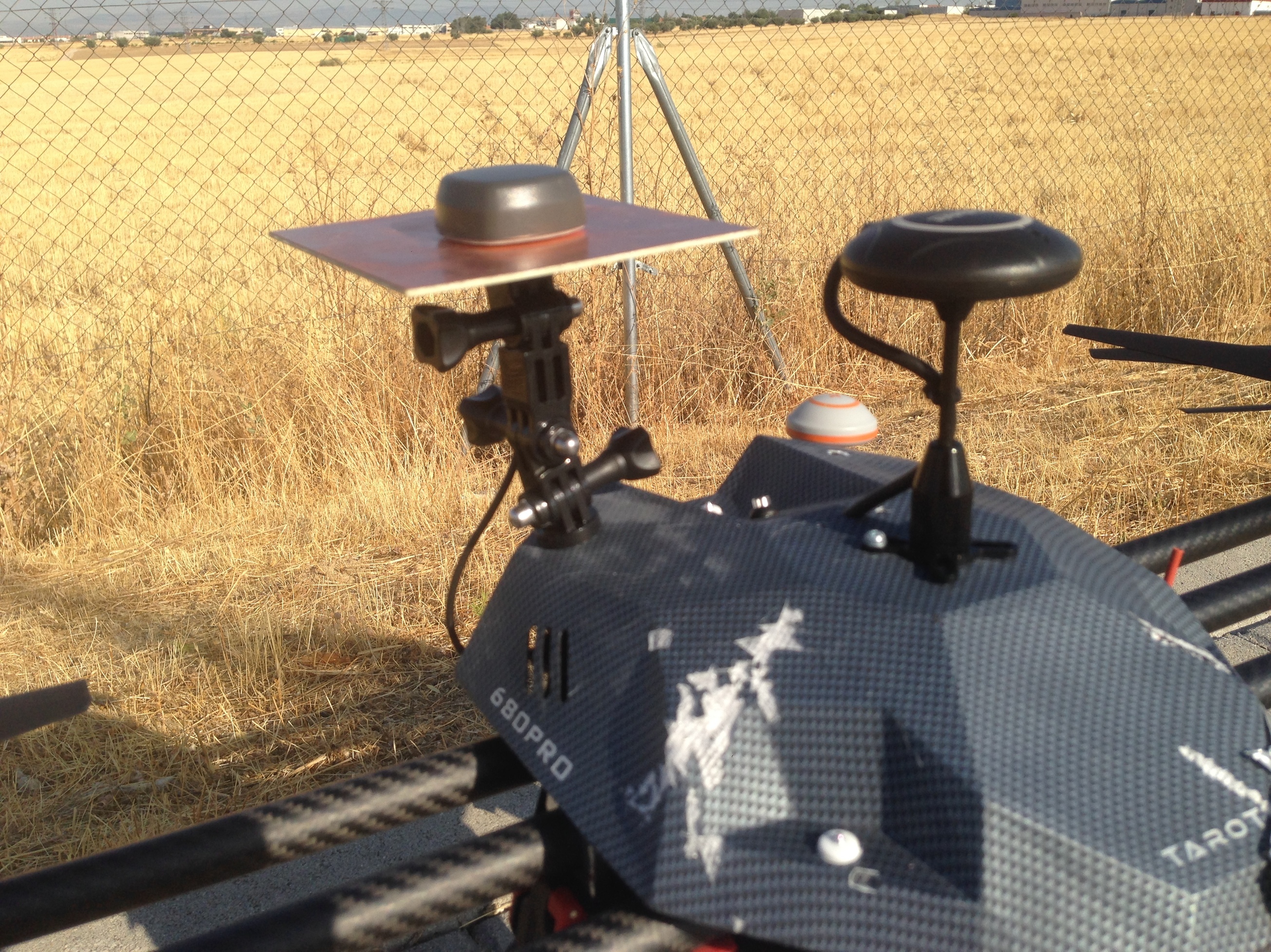
Ground planes are made of Raw PCB boards cut to 10x10cm squares and with the antenna cable straight down through a small hole.
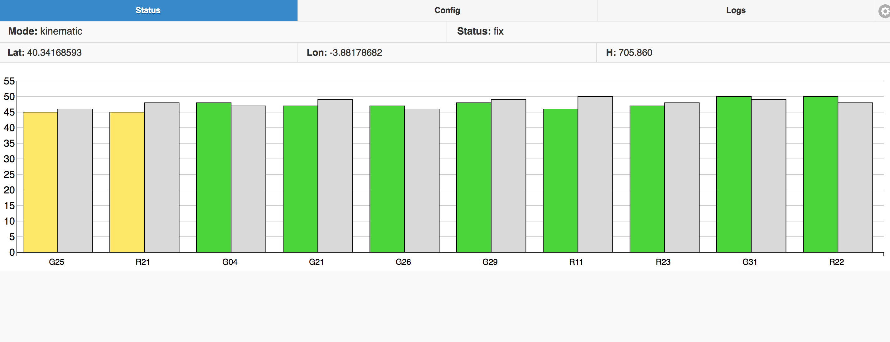
Finally, a screenshot of the SNR levels when fixed.
And the positions in RtkPlot. You can how the solution goes from single to float and the fixed.

And also the spots where the solution went very briefly from fixed to float and then back.

I will try this set-up again next monday and also check the results while flying. Because I am still not 100% confident that this solution is completely reliable every time. Again, I would really appreciate feedback or results from someone else in this or other configuration. I have some very important milestones close by and I need to have the RTK working reliable to ensure the future of our project.
Cheers!
2 Likes
by the way, does anyone know if it could be an issue of GPS injection by mission planner instead of the actual radio link? or did you already test it without mission planner in between? I guess this could be checked easily, although I cannot do it today.
Good afternoon Juan,
I have not been able to get the point that you have get, because I have not been able to adjust settings in the ReachViewApp.
Could you please send us an image about the way you connect your radios and how do you set up the ReachViewApp?
I am at Colombia and I have 3DR radios.
Thanks in advance
as requested by PM, here is a field report with working RFD900 settings:
reach_2:~/serial-radio$ python SiKset0.0.9.py --local --baud=57600 --show-parameters
ATI5
[1] S0: FORMAT=27
[1] S1: SERIAL_SPEED=57
[1] S2: AIR_SPEED=32
[1] S3: NETID=8
[1] S4: TXPOWER=27
[1] S5: ECC=0
[1] S6: MAVLINK=0
[1] S7: OPPRESEND=0
[1] S8: MIN_FREQ=915000
[1] S9: MAX_FREQ=928000
[1] S10: NUM_CHANNELS=50
[1] S11: DUTY_CYCLE=100
[1] S12: LBT_RSSI=0
[1] S13: MANCHESTER=0
[1] S14: RTSCTS=0
[1] S15: NODEID=1
[1] S16: NODEDESTINATION=65535
[1] S17: SYNCANY=0
[1] S18: NODECOUNT=2

reach_2:~/serial-radio$
Today, we worked in light rain with a 450m baseline. The radio signal had to push through 100m of forest/underbrush and the remainder was clear. Both Reach were running v0.4.9. The only changes to the “reach_kinematic_default.conf” was GPS_GLONASS_5Hz and increasing the minimum SNR from 35 to 40 and then to 45 to get more stable float values for the rover’s sub-optimal 45% sky view. Initially the radios were set for an air data rate (AIR_SPEED) of 64 (kbps), but there were times when the base’s grey bars were dropping out. The air data rate was decreased to 32(kbps) and the grey bars were rock solid for the duration.
For the day, there were some fixes, but mostly float, and I was not expecting anything more with such a limited sky view.
*a side note. at times when ReachView status was showing as “-”, I would wipe the water droplets off of the rover antenna, and it would immediately switch to “float”. A radome or a conical antenna would fix that problem, I think.
Than you bide, that’s good news and nice share. I would like to try this configuration. Regards…
1 Like
I have open that link, but i really can’t understand, I’m not familiar with code. May there us a step by step for installation direction?
If you are on Linux you can use a virtualenv. These should be basic instructions to download the code, setup a virtualenv so we don’t mess with your system’s python, and install the required modules.
git clone https://github.com/mr337/sikset.gitcd sikset-
virtualenv .venvorvirtualenv2.7 .venv source .venv/bin/activatepip install -r requirements.txt-
./sikset.py, may have to sudo that to get access to the radio device
If your on OSX these should be pretty similar, if your on windows I can’t help you. (pss come to the dark side)
If you get lost or have any issue feel free to ask.
I use win 7 pro…
What about putty, can i use it? But i don’t know the step.
Google is your friend, just type in a question like “How to use Putty” and you get a lot of good information.
Instructions
Save the download to your C:\WINDOWS folder.
If you want to make a link to PuTTY on your desktop: …
Double-click on the putty.exe program or the desktop shortcut to launch the application. …
Enter your connection settings: …
Click Open to start the SSH session.
More items…
Using SSH in PuTTY (Windows) - Media Temple
https://mediatemple.net/community/products/dv/204404604/using-ssh-in-putty-
1 Like
Another quick RFD900 field report from yesterday to help reassure of the usefulness of the radio links. ![]()
Yesterday was the same location as last report with approx 450m baseline. Set up the base and powered up the rover while sitting a few meters away. Got a solid fix in approx 1 minute. Moved the rover to the work location and had solid grey bars and float status very quickly. Same radio settings as last time, and had Reach slowed to 1Hz. Also I was using my workaround for simultaneously logging the RTCM3 file on the base and sending over the radio. As an aside: The workaround came in handy today when I forgot to power up the base radio and it saved me the 15 minute trip back to the base. RTK wasn’t needed for today’s work, so I just post-processed the logs. In case you’re wondering, I’m not reporting on the position results because they are not great. This is because of the 12-15 meter trees beside and the 60+ meter trees not too far away. Post-processing tweaks are helping, and I found out that 10 minute occupation times on a windy day are not enough. 30+ minute on a calm day worked much better in this jungle.
1 Like
Could you guys post some pictures of your antenna setups? I have trouble getting a fix with the RFD modems on (I uses 868 european models).
Here’s my setup:
- Reach base station, RFD868 on the serial port, powered through the reach
- Reach rover, Navio with RFD 868 on the USB port via FTDI, and reach on the serial 6 wire port.
I think I’m doing something wrong with antennas because:
- When I let the reaches communicate with wifi, everything is fine and I get a real fast fix.
- When they keep communicating via wifi, but I turn on the radio modem of the base station, I get no fix.
- When I turn off wifi and inject DGPS in Mavlink, I get nice obj() dgps data, grey bars in the sattelite bar chart, but still no fix.
It’s as if the radio modem is destroying the satellite data.
What is a good antenna setup?
Did you tried to power modem externally ? I mean not through Emlid, modem are energy hungry.
Yes. As I recall that led to some 5V/3.3V logic issues. Should I try it again?
what was your best range in line of sight and non line of sight situation using rfd900?
Im interested to use this radio to get longer range
HI, everybody . i need you r help guys please. i have two rfd900+ module and i need to control 2 servo motors and one dc motor wireless using Arduino in the transmitter side with two joystick and another Arduino to read the incoming signal from the RFD900+ module, i have write booth transmitter and receiver code in the Arduino i also make the configuration setting for the module.the issues i face as follow : when i power off then on the transmitter or the receiver during operation the module fail to reconnect again . the green led keep blinking at the transmitter and receiver module.it only connect again if i power off booth module and connect them again . some times i face the same issue when also signal lost and back . here is my simple code . transmitter code :const int potPin1 = A0; // Pin for potentiometer 1
const int potPin2 = A1; // Pin for potentiometer 2
const int potPin3 = A2; // Pin for potentiometer 3
void setup() {
Serial.begin(57600); // Set baud rate for serial communication
// Serial1.begin(57600); only used with arduino mega 2560
}
void loop() {
int servo1Angle = analogRead(potPin1);
int servo2Angle = analogRead(potPin2);
int motorspeed = analogRead(potPin3);
int mapped_servo1Angle = map(servo1Angle , 0, 1023, 0, 180); // Map potentiometer reading to servo angle range
int mapped_servo2Angle = map(servo2Angle , 0, 1023, 0, 180); // Map potentiometer reading to servo angle range
int mapped_motorspeed = map(motorspeed , 0, 1023, 0, 250); // Map potentiometer reading to motor speed range
Serial.write(9); // Write a marker to identify servo1Angle value
Serial.write(mapped_servo1Angle); // Send servo1Angle value
Serial.write(10); // Write a marker to identify servo2Angle value
Serial.write(mapped_servo2Angle); // Send servo2Angle value
Serial.write(3); // Write a marker to identify motorspeed value
Serial.write(mapped_motorspeed); // Send motorspeed value
// Serial.print("servo1Angle: “);
//Serial.print(mapped_servo1Angle);
// Serial.print(” ");
// Serial.print("servo2Angle: “);
// Serial.print(mapped_servo2Angle);
//Serial.print(” ");
// Serial.print("motorspeed: ");
// Serial.println(mapped_motorspeed);.
delay(10);
}
the receiver code :#include <Servo.h>
const int servo1Pin = 9; // Pin for servo 1
const int servo2Pin = 10; // Pin for servo 2
const int motorPin = 3; // Pin for DC motor
Servo servo1;
Servo servo2;
void setup() {
Serial.begin(57600); // Set baud rate for serial communication
Serial1.begin(57600);
servo1.attach(servo1Pin); // Attach servo1Pin to the servo object
servo2.attach(servo2Pin); // Attach servo2Pin to the servo object
pinMode(motorPin, OUTPUT);
}
void loop() {
if (Serial1.available() )
{
int marker = Serial1.read(); // Read the marker

if (marker == 9) { // servo1Angle marker
  int servo1Angle = Serial1.read(); // Read the servo1Angle value
  servo1.write(servo1Angle); // Set the servo1 angle
  Serial.print("Servo 1 Angle: ");
  Serial.print(servo1Angle);
  Serial.print("    ");
}
else if (marker == 10) { // servo2Angle marker
  int servo2Angle = Serial1.read(); // Read the servo2Angle value
  servo2.write(servo2Angle); // Set the servo2 angle
  Serial.print("Servo 2 Angle: ");
  Serial.print(servo2Angle);
  Serial.print("    ");
}
else if (marker == 3) { // motorspeed marker
  int motorspeed = Serial1.read(); // Read the motorspeed value
  analogWrite(motorPin, motorspeed); // Set the motor speed
  Serial.print("Motor Speed: ");
  Serial.println(motorspeed);
}
}
}
i will be so glad for your help
Hi @anwar1098,
Welcome to the forum!
We haven’t tested this particular setup with Arduino and custom code, so I can hardly suggest anything specific. Hopefully, someone from our users who’s experienced with it can ayou on dvise something.