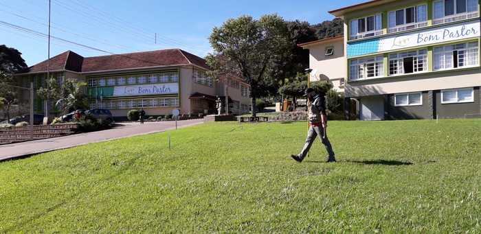
Rafael Scopel, a surveyor at the Escola Bom Pastor school in Brazil, recently prepared a land surveying workshop for his students with a set of Reach RS+.
The main goal was to re-observe an existing geodetic control network—six control points spread throughout the school grounds.
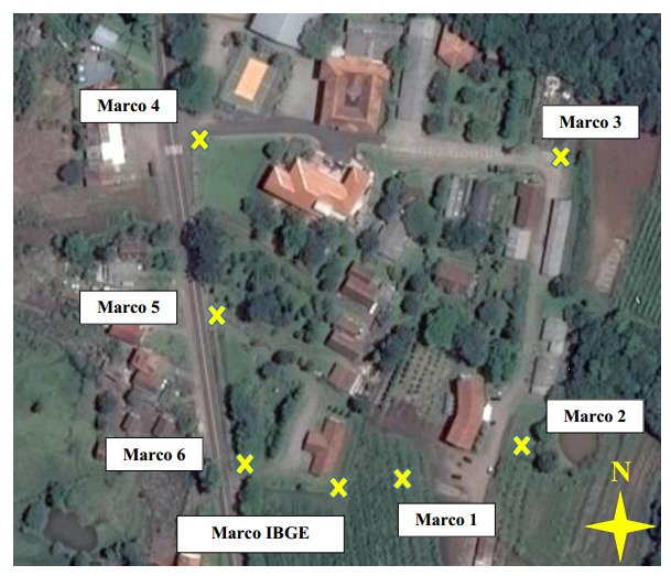
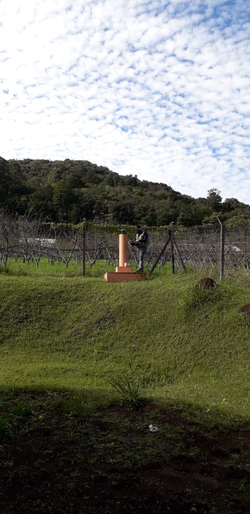
Geodetic control network at the Escola Bom Pastor school
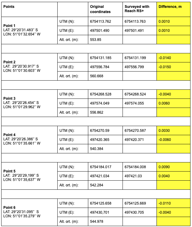
With a set of Reach RS+, Rafael measured all the points in RTK mode and got the results shown in the table below. In order to collect data, he used ReachView app.
The yellow column represents the difference between the original points and coordinates surveyed with Reach RS+. All the WGS results were converted into UTM with AutoCAD Civil 3D.
Results of surveying converted into SIRGAS 2000, zone 22S
In the future, students will do the same work with a total station and re-assure that benchmark points are surveyed correctly.
“As a user, I must say that Reach RS+ is a very easy-to-use GNSS receiver at an affordable price. It is a great deal!”— Rafael Scopel de Lima, Surveying Teacher at the Escola Bom Pastor school
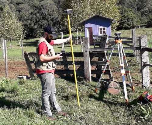
It is probably also useful to hold the survey pole vertically if you try to measure something with such accuracy - I guess that is just a demonstrative picture… .
How were the original points located? I would really encourage you to teach about localization. Having such a network is fine point to point, but if it is truly a network and meant to encompass a subject you will get much better accuracy with localization. Otherwise you will never know if any points are out of tolerance as they relate to the “network”.
I think in that photo, he was using the rover pole to rest on while watching some YouTube videos on his lunch break. Get’s exhausting cutting thick line for 6 control points! jk… great post!
Since this topic gained so much attention… that’s my work. In 2017, I’ve created a network of geodetic landmarks, with another pair of equipment (South S86T as Base and Astech Promark 3 as Rover), following the Brazilian Regulations. In 2019, I’ve checked the same geodetic landmarks, this time with Reach RS, and that was the result. The base was placed like this:
Curious. Where exactly is the elevation measured to on one of these monuments in relation to the ARP (Antenna Reference Point) of the Reach RS? Do you use the orthometric height recorded in the PDF document (your example) or do you use the WGS84 ellipsoid height (is this it: Altitude Geométrica(m) 552,095 or is this orthometric height)? What is this? Geoid height?: MC -51
Since a KNOWN POINT, do you enter the antenna height additionally when you MANUALLY enter your coordinates & elevation of the PDF document?
I am not familiar with these types of monuments or trig points, so nice to learn about them and how they are used with the Reach equipment.
Tim the referred height is ellipsoidal, does not show the monograph from which to take the height. Rafael could you send me the data of the base to make a postprocess with another IBE station and thus verify the geodetic coordinates