Hello, I have the same problem here. I already tested 2 different Raspberry Pi’s, a Model A and a Raspberry Pi 2 Model B, both with fresh SD cards and I don’t have any RC signal. Something different from the other guys is that I don’t have the “No pigpio interface for RCInput”, but when I run the Barometer test very weird vales are being returned:
I found that if I load a new SD card and run updates using apt-get update; apt-get upgrade and/or use raspi-config this would happen. Did you happen to update the system packages?
Thank you for your answer, yes I did, at least I executed app-get update and raspi-config.
I started again from scratch, just wrote the image to the SD card and installed APM, the Barometer test now shows normal and coherent values, unfortunately the PPM input is still not being detected.
Running the PPM C++ example, the initialization runs just fine, but no input is ever detected, the function ppmOnEdge() never get called.
Hello, I tried 2 different receivers, one is a Walkera RX705 with a Data Bus Port (PPM compliant), the other is a normal PWM receiver, connected through the original 3DR PPM encoder, both with the same results.
I wish I could have an scope, unfortunately I can´t have access to one at this moment.
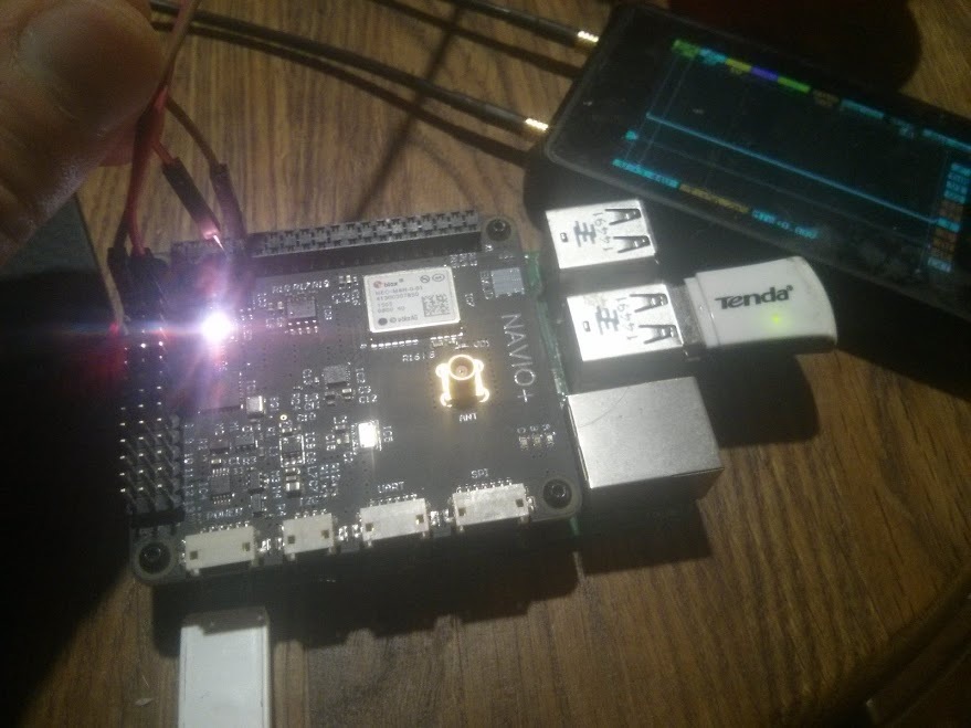
Thank you Igor for your answer, yes it is getting power through a dedicated BEC.
Even the blue Led of the 3DR PPM Encoder is blinking faster according to the throttle position.
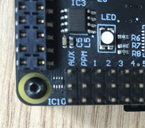
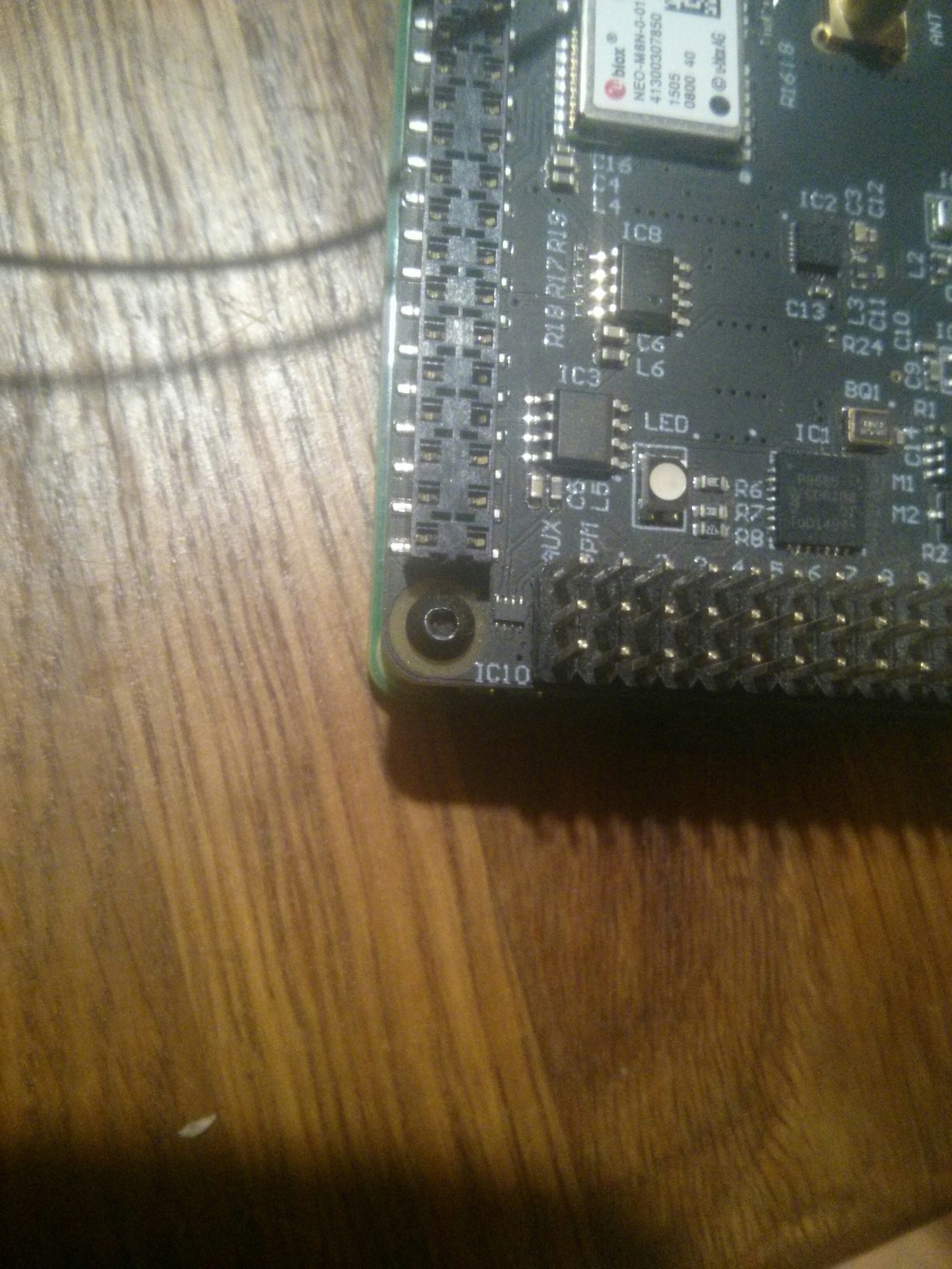
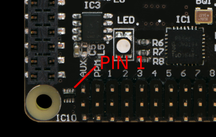
There is only IC10 - NTS0102GT logic level converter in the way of the signal. Can you visually inspect it? It is located near servo connector. Could you by any chance have made any modifications to the board that would affect it?
Hi, it seems I have the same problem on Navio+ and RPI2.
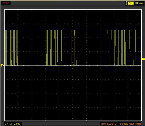
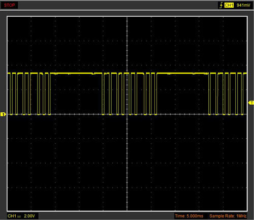
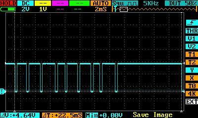
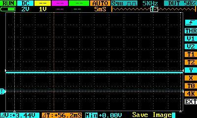
As a PPM generator I had used arduino nano with 5v output. On oscilloscope I see proper PPM signal and on Navio’s GPIO4 I see stable continuous +3.3v. I also played with different signal frequency to Navio’s PPM input f.e. 1sec HIGH and 1sec LOW and see the same continuous +3.3v on Navio’s output. IC10 is also on his place. PPM decoder started but no output as logic level always “1”. So, it seems it is hardware problem. May it be that IC10 (logic level converter?) has been burned someway. What this can be? Can I fix it myself?
P.S. I have checked the RPI by connecting DSO Quad’s signal generator wires to GPIO4 directly and see GPIO input on raspberry, also with signal generator Navio’s PPM decoder showing something as there is level == 0 condition and signal generator produces 0 level.
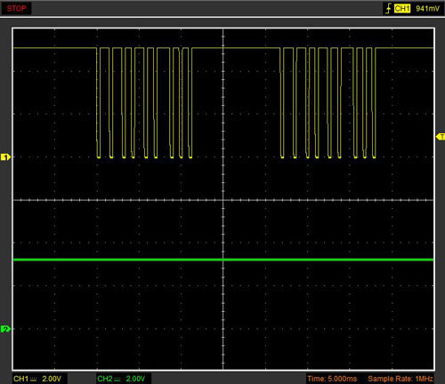
Output from PPM generator, it is proper 22.5ms signal with Vmax up to 5v:
It looks like you have done a good job on debugging the issue. Could you send me a PM with your order number so that I could help you with repair or replacement?
Ouch! One of the 3D print housing for NAVIO+ that is show off in this forum has fat feet on the cover and squash my IC10 from PCB:-( I have been trouble shooting on R/C signal loss and found the picture above that is very odd place of the chip!
Anyway, I would like to use my NAVIO+ again.
Is it possible to ask to repair my NAVIO+ or purchasing NTS0102GT chip ?
If you don’t have a hot air gun or don’t want to replace it yourself you can ask for help in any local mobile repair company, should not take more than a couple of minutes.
I’ve just order the chip on Digi.
One thing to make sure, could you show the direction(pin1) of chip of IC10?
My chip is completely removed and gone, and no way to find pin1 position.