Here’s an update.
It has been a bit windy this week so I I have focused on timing. A bit of soldering and a bit of programming and I have trigger for the reach that is synced with the DJI photo to a timing accuracy of about 30ms. It is difficult to be more precise than that as I have yet to find a millisecond clock to take photos of. With my reach results in UTC and with a 0.1 second UTC clock in the image my reach time marks, with a predetermined offset, will get the time right in the displayed clock 98% of the time.
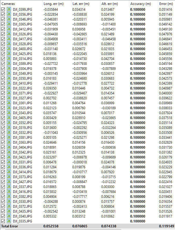
30ms equates to an along track error of 15cm at 5m/s. Couple this with post processed kinematic GPS accuracy of say +/- 10cm horizontally and + 20cm vertically and the error budget looks like …
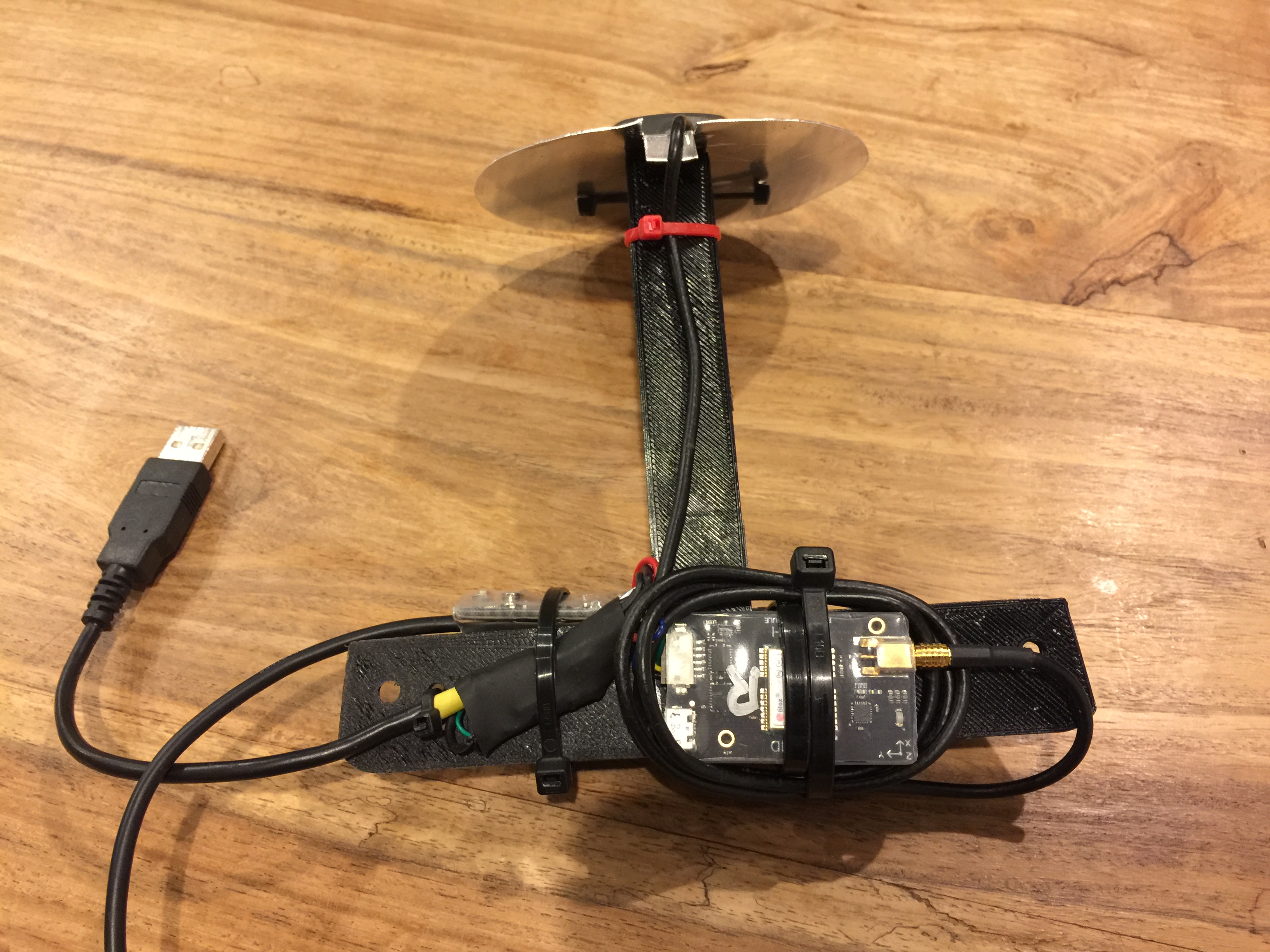
The workflow is bitty and my electronics appalling, but if anyone is seriously interested in this then e-mail me simon.allen@spatialanalytics.com.au. I assume that my method of timing is similar to that which Sentera do to tie in their IR camera, but my method does not involve opening the drone and of course provides post processed kinematic accuracy on a DJI Phantom. Of course now there is a trigger then it can be used to activate additional cameras.
Just thought I would share and update.
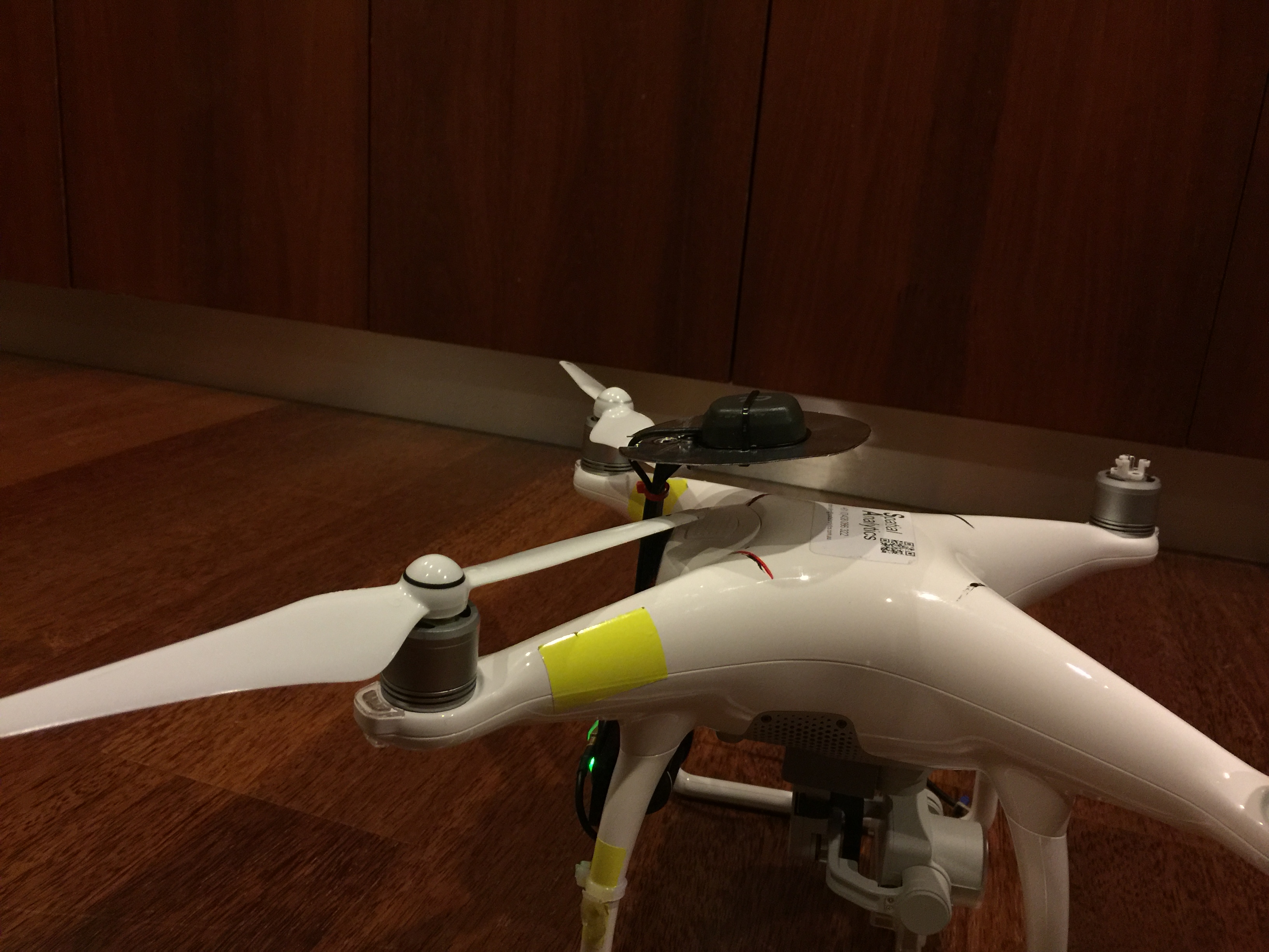
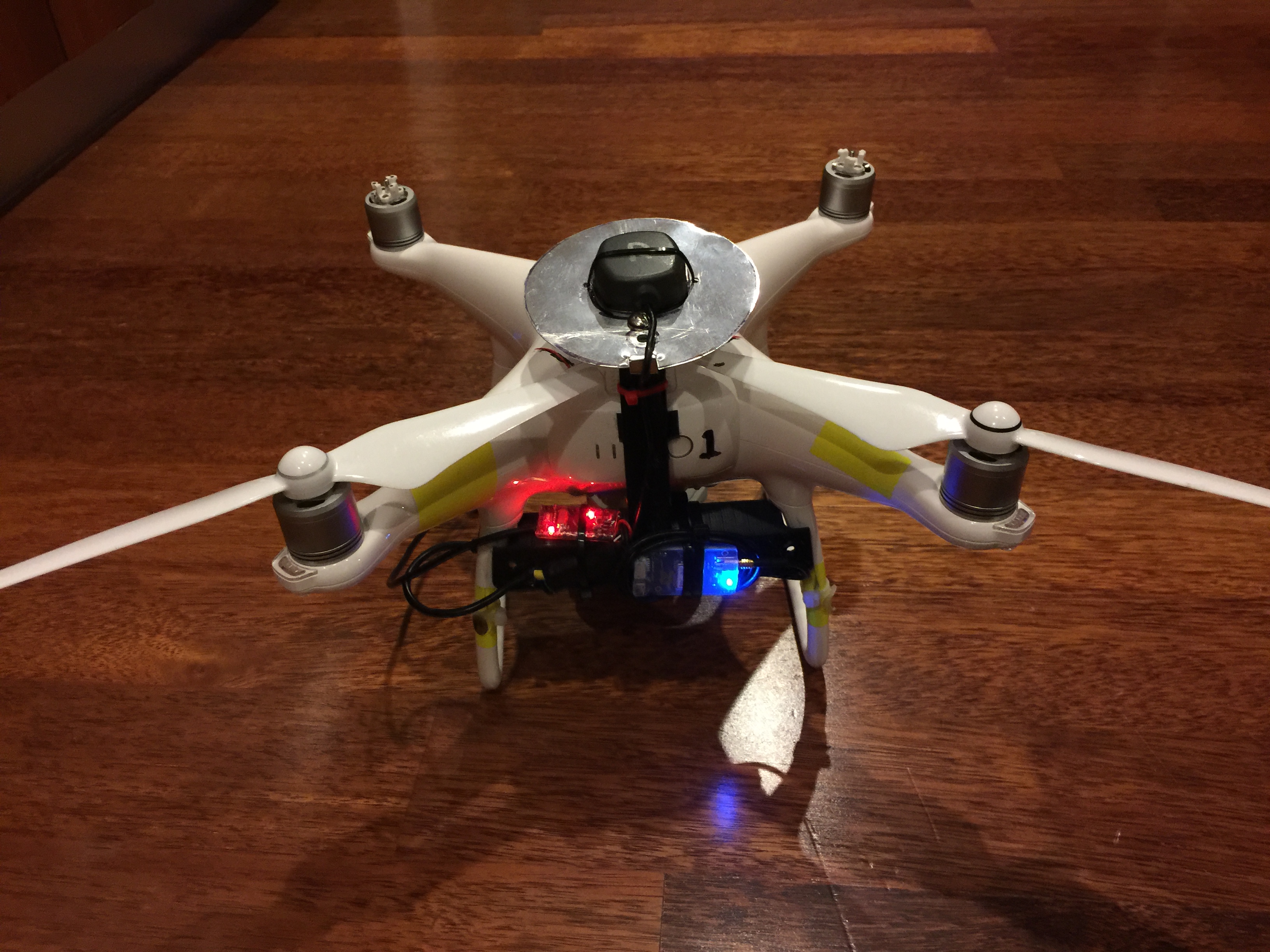
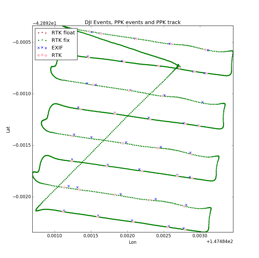
Reach unit mounted on Phantom 4. I ran two missions (at different altitudes, hence slighly different lines) , the second mission was fully FIX and I successfully captured the Phantom 4 photo-timing signal onboard the reach for both missions. This allowed me to inject the PPK positions into the EXIF headers of the images prior to processing in normal photogrametry software.
Big excitement for me is that this is now a fully automatic process rather than a mandraulic data shuffle.
Hi Simon, this is great work, I’ve been trying to ‘sniff’ the shutter activation on the Inspire and have that event recorded by the reach with little success and have been following your work. I have a cradle constructed that’s mounted on the Inspire 2 and have just been logging mapping flights and manually updating the exif as close as I can get. Not bad results so far and at least the z values are closer to our local mapping datum after PPK and connection to our CORS network so this has benefit. Would you be willing to share how you are getting the shutter event from you Phantom as I would think this will be similar to other DJI drones. PS I’m a Geomatics researcher at Uni so no commercial end here. Thanks Conor.
Hi Simon, your posts are immensely helpful, welcome cliff notes on a skipped class. I’m a cinematographer experimenting with photogrammetry/modeling for dimensional control with the Inspire 2 / X5S cam. Attempts to model rather complex industrial structures have produced the usual frustrations… stitching errors, blobby meshes, point cloud noise etc. The gps variations in our data sets (orbits, nadirs, columns etc) is killing us… Possible to suggest how we might use the Reach with the I2 like you did with the P4?
The absolute biggest critical element in 3D structure work is the camera calibration. Nail this and everything else just falls into place (literally) in terms of fuzzy clouds. Are you trying to mesh? I have found that working directly with the point cloud is the answer for complex shapes.
If Pix4DCapture works with I2, I have a script that marries the pix4D millisecond timing events with the raw 5Hz position file from the reach and interpolates the position within the 0.2sec intervals.
Thanks so much for your helpful reply. Pix4DCapture does work with the I2. We will need to test in prep for the specific capture strategy for this structure as we haven’t used it - usually use DDploy for nadirs, Autopilot for orbits + Go for columns & free flight - too many cooks! Only question for me, and this may be a dumb one but I haven’t gotten to test it yet, is if orbits / circular flights can be based on a manually set POI, or rather if one defines on a map overlay like one does with grid capture plans… if we can’t do tight manually defined POI orbits it will get unsafe given the environment and we’d need to add orbit data sets from an app that allows for this…we’ll be flying tight circles above multiple vertical cylinders. It’s a rather complex structure & we’re seeking dimensional control not only of the cylinder tops but on lower structural bars holding them together as well. So yest that script would be most appealing! And may I ask how ones get the married times/positions into the image metadata?
Great. There are some functionality concerns w/ Pix4DCapture vs other guidance software (can’t set focus strategy to center/subject with altitude offsets for tight orbits for example, something of a damper on on-site improvisations given obstacles) but we can probably find workarounds for this in the field, perhaps with their freefly mode. I would be keen to give your script a try & would have a few workflow questions if you’d allow. Would be happy to provide project details, results etc. Would that work for you?
Flew a mission at 10m/s to see what impact any remaining timing errors may have. Pretty happy with the results.
Using the launch point as a single check point the final orthomosaic displayed a 12cm shift. When corrected to for this with a global shift the final results for the other check points were, wait for it… I will let you know tomorrow.
How do your power the emlid? I’m trying to do similar with phantom 3 but want to keep it light. Why didn’t you mount the antenna more closely over the top of the camera? Seems like an unnecessary horizontal shift.