You already know your baseline bearing and distance if you set the end points with RTN. Simple inverse using coords.
When I start a boundary project, I use the RTN rover and set two points for the static M2’s approx 200-300m apart depending on how far I’ll be from the units. Usually on a 300 acre site, I’m no more than 300-500m from the static M2’s depending on the shape of the tract. I then proceed to locate corners, creeks or roadways using the RTN rover. All this time per point located, I’ve got 3 baselines per point. If I loose cell coverage (which in my area is minimal), I’ve got a closed loop (triangle) for every point. If it’s an important point such as a boundary corner and I’m still without RTN, I’ll occupy a minimum of 30 minutes especially in high multi-path areas. Every point has a closed loop to verify the accuracy. The beauty of this is short baselines and verification with closed loops. Accuracy is greater with short baselines. I’ve checked my RTN positions with PP and a lot of times it’s <1 cm both horizontal and vertical.
Touching on a slightly diverging subject, I did that process not two days ago to get an azimuth between two points on an arbitrary polygon that students will have to work with. I’m trying to figure out why there’s an effect that my knowledge cannot account for (I never did surveying professionally and my courses are nothing more than vaporous memories now).
I converted the 4 points from the receiver’s NAD83 coordinates to a MTM projection and then simply calculated dX/dY then the azimuth between points. Just to double check, I fed the NAD83 coordinates straight in INDIR. The values are similar enough and when I sum up the interior angles, both methods close precisely but there’s a constant ~1° rotation between the corresponding segments. I’m guessing it has to do with taking the meridian convergence into account (even though I disabled the 3D flag in the tool) but I’m wondering if you have the answer from the top of your head.
At least it won’t have an effect on the project as it’s only a pedagogical setting.
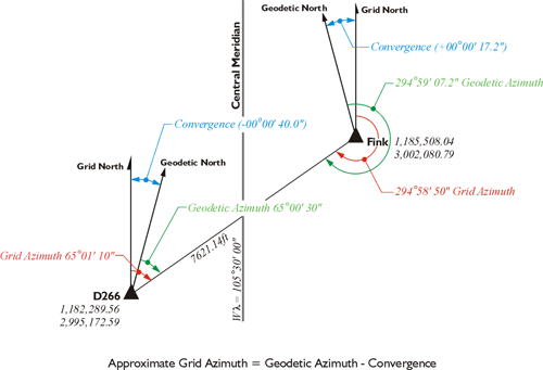
It appears it’s giving a geodetic inverse, not on the actual mapping datum. There’s a difference between “plane (grid)” azimuth and “geodetic” azimuth. From the help menu:
The INDIR Inverse-Direct computation tool performs either a geodetic direct or inverse computation. Direct uses a starting point’s geographic coordinates, an azimuth and a distance to compute the geographic coordinates of the end point. Inverse uses geographic coordinates of two points to compute azimuth and distance.
You would need to convert the NAD83 geographic coords to the local grid system as we do here in the USA. Just as OPUS computes the geographic coords it also gives state plane grid coords (user selected). This is what we use and reference in ground land surveying.
Back in the pre GPS days, we oriented all our surveys to SC State Plane NAD27 or NAD83 azimuths. We determined the azimuth by either solar observation or by astronomic observations. You had to have accurate time and know your geographic within +/- 100’. We usually scaled the position from a USGS quadrangle sheet. The computation was either done in the field using HP41CX or HP48 or done in the office using USNO software. The computation gave the “true” (astronomic) azimuth to the observation mark. The scaled geographic coords were also used to determine the convergence angle (theta) to apply to the astro azimuth to obtain the grid azimuth.
Thanks for the refresher, that’s exactly what I thought it was (the funny thing is I do know that stuff as I add the convergence information on the topographic maps I produce).
In this case, our survey is located right at the western edge of the local zone, as far as it can get from the central meridian, so it’s entirely normal grid and geodetic north diverge a lot.
We are in Central Texas and half of our jobs are right at the mid-point of where TX-C and TX-SC lap over. Yeah, that’s fun to startup a new project on…
It’s pretty in depth for all the formulas relating to conversion of geodetic coords to state plane grid coords. The formulas aren’t that hard, I had programmed some of these year’s ago for in house use. I don’t think these would apply for your area, but it’s a good technical read.
You need to review manual. It has an excellent traverse example on pages 53-61 (printed no.s) of typical terrestrial traverse (same as GNSS traverse) between control monuments, reduction of ground to grid, t-T correction, latitude-departure computations, adjustment of traverse, etc. You should read manual from the beginning to end.
I’ll see if I can find an old copy of the NAD27 manual from my early days, this is basically what help me comprehend geodetic control methods and computations growing up in this profession from the late 60’s when I first started surveying with my dad and became the professional I’m today
What’s the typical mapping datum in Denmark or your area. We convert everything to state plane grid system here. Your geodetic agency should have something published like this.